
Air-conditioner compressor structure with compressor damping block and air-conditioner outdoor unit thereof

An air-conditioning compressor and compressor technology, which is applied in the direction of machines/engines, mechanical equipment, liquid variable capacity machinery, etc., can solve the problems affecting the consumer's use environment and the vibration of the outdoor unit of the air conditioner, etc.

Inactive Publication Date: 2014-08-27
GUANGDONG CHIGO AIR CONDITIONING
View PDF6 Cites 6 Cited by
  • Summary
  • Abstract
  • Description
  • Claims
  • Application Information

AI Technical Summary

Problems solved by technology

The axial vibration on the compressor damping feet is transmitted to the chassis, while the lateral vibration on the compressor damping feet makes it collide with the chassis connecting bolts on the chassis, and the chassis connecting bolts transmit the vibration to the chassis, thus making The vibration of the outdoor unit of the air conditioner produces noise, which affects the use environment of consumers, especially for the outdoor unit of the air conditioner that has been used for a long time, the noise effect caused by the vibration is more prominent

Method used


Image

  • Air-conditioner compressor structure with compressor damping block and air-conditioner outdoor unit thereof
  • Air-conditioner compressor structure with compressor damping block and air-conditioner outdoor unit thereof
  • Air-conditioner compressor structure with compressor damping block and air-conditioner outdoor unit thereof

Examples


Embodiment Construction

[0013] The present invention will be further described below in conjunction with specific embodiment:

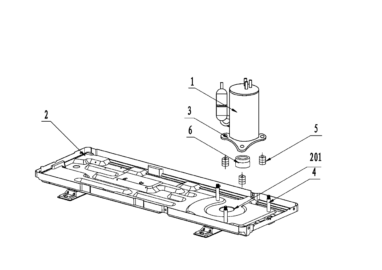
[0014] See attached figure 1 to attach figure 2 As shown, the installation structure of an air conditioner compressor with a compressor damping block described in this embodiment. The air conditioner compressor installation structure includes a compressor 1, a chassis 2 at the bottom, compressor mounting feet 3 fixed on the bottom of the compressor in an equilateral triangle arrangement, three chassis connectors 4 fixed on the chassis 2, and The compressor is installed with a compressor damping foot 5 on the end face of the foot 3 . Wherein, in order to reduce the impact of the vibration of the compressor 1 on the chassis 2, the three compressor mounting feet 3 on the bottom of the compressor are arranged and fixed on the bottom of the compressor in the form of an equilateral triangle with the compressor 1 as the center point. When the compressor 1 vibrates, the lateral ...


PUM


Abstract

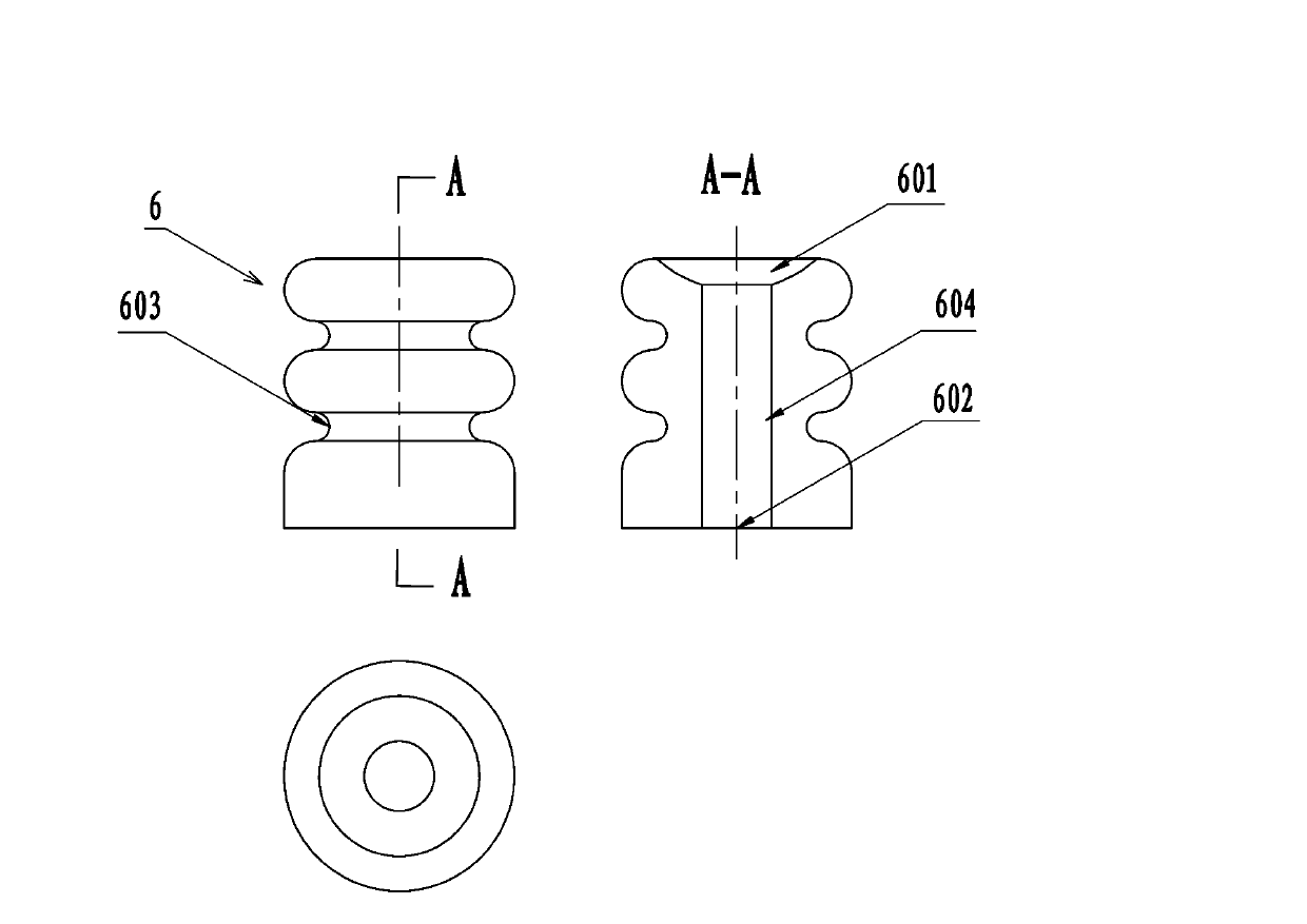
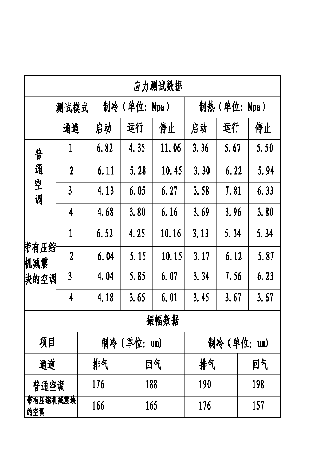
The invention provides an air-conditioner compressor mounting structure. The air-conditioner compressor mounting structure comprises a compressor, a chassis, compressor mounting feet which are arranged and fixed at the bottom of the compressor in an equilateral triangle mode, three chassis connecting pieces which are used for enabling the compressor mounting feet to be fixedly connected to the chassis, compressor damping feet which are placed on the upper end faces of the compressor mounting feet, and a cylindrical compressor damping block. An inward recessed arc-shaped structure which is in contact with the bottom of the compressor and is matched with the bottom of the compressor is arranged on the upper end face of the compressor damping block, a plane structure which coincides with the contact face of the chassis is arranged on the lower end face of the compressor damping block, and a damping groove is formed in the peripheral direction of the cylindrical compressor damping block. In the mounting process, the upper end face of the cylindrical compressor damping block is tightly attached to the bottom of the compressor and compresses the bottom of the compressor, the lower end face of the cylindrical compressor damping block is attached to a round damping block mounting groove formed in the chassis and compresses the round damping block mounting groove, and the round damping block mounting groove is placed in the central position among the three chassis connecting pieces. The compressor mounting structure effectively improves the stress condition of the overall mounting structure of the compressor.

Description

technical field [0001] The invention relates to the technical field of air conditioners, in particular to an air conditioner compressor structure with compressor damping blocks and an air conditioner outdoor unit thereof. Background technique [0002] The compressor in the existing air conditioner outdoor unit is generally fixedly installed with a compressor mounting foot in the form of an equilateral triangle structure at the bottom. When installing, first set the compressor mounting feet on the chassis connecting bolts. After the installation is in place, put the compressor damping feet respectively on the upper ends of the compressor mounting feet, and then tighten the nuts to achieve locking. When the air conditioner is running, the compressor will generate vibrations in the axial and lateral directions when it is working, and the vibrations will be transmitted to the shock-absorbing feet of the compressor. The axial vibration on the compressor damping feet is transmitt...

Claims


Application Information

Patent Timeline
IPC IPC(8): F04B39/00
Inventor 林灿洪高永胜尤顺义邓永平
Owner GUANGDONG CHIGO AIR CONDITIONING
Learn More