Optical link for connecting antenna with reader-writer in passive RFID system
A technology of reader-writer and optical link, which is applied in the direction of instruments, cooperative devices, computer components, etc., can solve the problems of small identification tag range and low identification accuracy, and achieve improved receiving sensitivity, improved distribution range, The effect of low optical link loss
- Summary
- Abstract
- Description
- Claims
- Application Information
AI Technical Summary
Problems solved by technology
Method used
Image

Examples
Embodiment 1
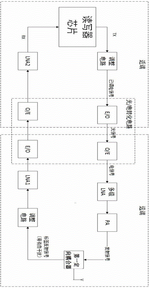
[0065] Example 1, such as figure 1 As shown, an optical link connecting an antenna and a reader in a passive RFID system is provided, including a reader chip for transmitting downlink signals and receiving uplink signals; the first electrical signal-to-optical signal module and the read-write chip connection, used to convert the received signal into an optical signal, and input the first optical signal to electrical signal module after optical fiber transmission; the first optical signal to electrical signal module is used to convert the received signal into an electrical signal , and input the multi-stage low noise amplifier; the sequentially connected multi-stage low noise amplifier and power amplifier are used to amplify the radio frequency signal output by the optical signal to electrical signal module, and deliver the amplified radio frequency signal to the first directional The input end of the coupler; the first directional coupler is used to cooperate with the back-end...
Embodiment 2
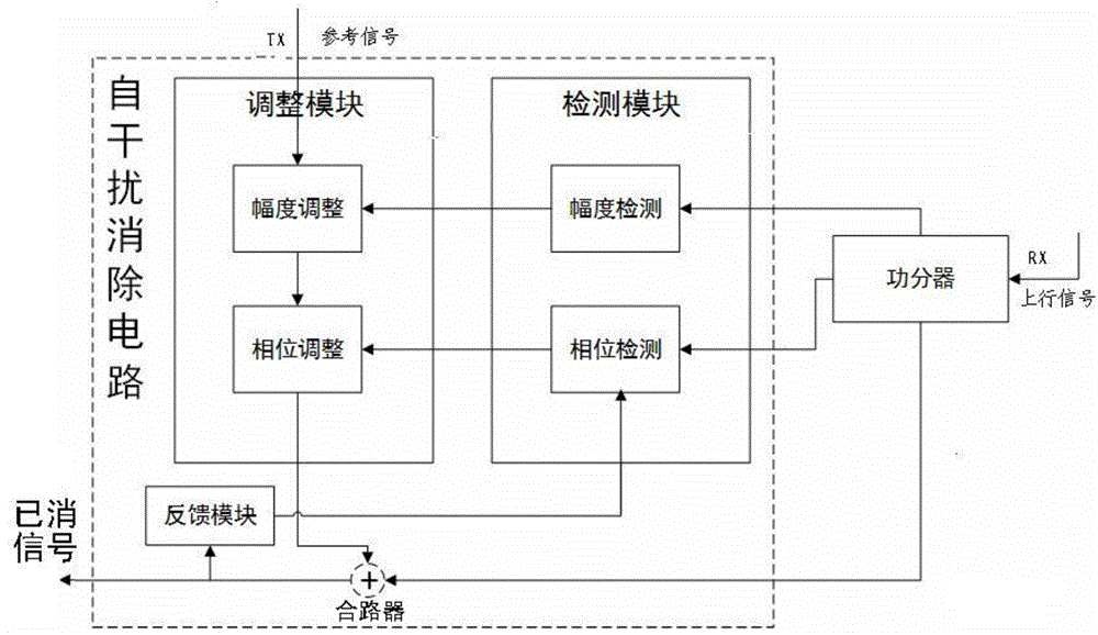
[0070] Embodiment 2: On the basis of Embodiment 1, this embodiment provides an optical link connecting an antenna and a reader in a passive RFID system, in which a self-interference elimination circuit is provided, such as figure 2 Shown; This self-interference cancellation circuit can guarantee the receiving sensitivity of the system.
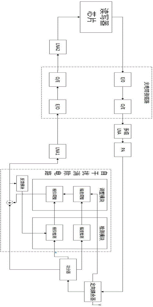
[0071] Will figure 2 The shown self-interference cancellation circuit is set at the far end of the optical link connecting the antenna and the reader in the passive RFID system, such as image 3 shown. Specifically, an adjustment circuit is provided between the first directional coupler and the first low-noise amplifier; the adjustment circuit includes a power divider and a self-interference elimination circuit; the optical link is applied to a small number of remote distribution antennas , the range of passive electronic tags is more complicated, and the leakage of downlink signals is serious.
[0072]The self-interference elimination ci...
Embodiment 3
[0075] Embodiment 3: On the basis of Embodiment 1 and Embodiment 2, this embodiment provides an optical link connecting an antenna and a reader in a passive RFID system, and the link is provided with digitally controlled self-interference Elimination circuits such as Figure 5 shown.
[0076] The self-interference cancellation circuit with digital control is divided into four parts: detection module, adjustment module, feedback module and buffer. The detection module includes: an amplitude detection module, a phase detection module, and a control center. The adjustment module includes: an amplitude adjustment module and a phase adjustment module. The basic principle is: the uplink signal is input to the power divider, and the power divider divides the uplink signal into three paths, one path of large-amplitude signal is input to one of the inputs of the combiner, and the other two paths of small-amplitude signals are respectively input to the detection module In the amplitu...
PUM
 Abstract
Description
Claims
Application Information
 - R&D Engineer
- R&D Manager
- IP Professional
- Industry Leading Data Capabilities
- Powerful AI technology
- Patent DNA Extraction
Browse by: Latest US Patents, China's latest patents, Technical Efficacy Thesaurus, Application Domain, Technology Topic.
© 2024 PatSnap. All rights reserved.Legal|Privacy policy|Modern Slavery Act Transparency Statement|Sitemap