Image processing apparatus, projector, and image processing method

a technology of image processing and projector, which is applied in the field of image processing apparatus and projector, can solve the problems of undesirable expansion of luminance values in image processing, and achieve the effect of expanding the range of luminance values

Active Publication Date: 2016-08-09
SEIKO EPSON CORP
View PDF57 Cites 4 Cited by
  • Summary
  • Abstract
  • Description
  • Claims
  • Application Information

AI Technical Summary

Benefits of technology

[0007]An advantage of some aspects of the invention is to expand the range of the distribution of luminance values in image data by using an expansion factor that matches the position of a light attenuation member.
[0015]Still another aspect of the invention provides an image processing method including generating a drive signal to drive a light attenuation member that attenuates light radiated from a light source based on a difference between first transmittance and second transmittance, the first transmittance being a target value calculated based on image data and the second transmittance being detected based on the position of the light attenuation member, calculating an expansion factor based on the first transmittance and the second transmittance, expanding the range of the distribution of luminance values in the image data based on the expansion factor, and outputting the expanded image data to a driver that drives a light modulator that modulates light incident thereon. According to the image processing method, the range of the distribution of the luminance values in the image data is expanded by using an expansion factor that matches the position of the light attenuation member, unlike a case where the expansion factor is calculated based only on the first transmittance.

Problems solved by technology

Therefore, in the course of movement of the light attenuation plate, the luminance value expanded in the image processing undesirably does not match the changed amount of light resulting from the movement of the light attenuation plate in some cases.

Method used


Image

  • Image processing apparatus, projector, and image processing method
  • Image processing apparatus, projector, and image processing method
  • Image processing apparatus, projector, and image processing method

Examples


Embodiment Construction

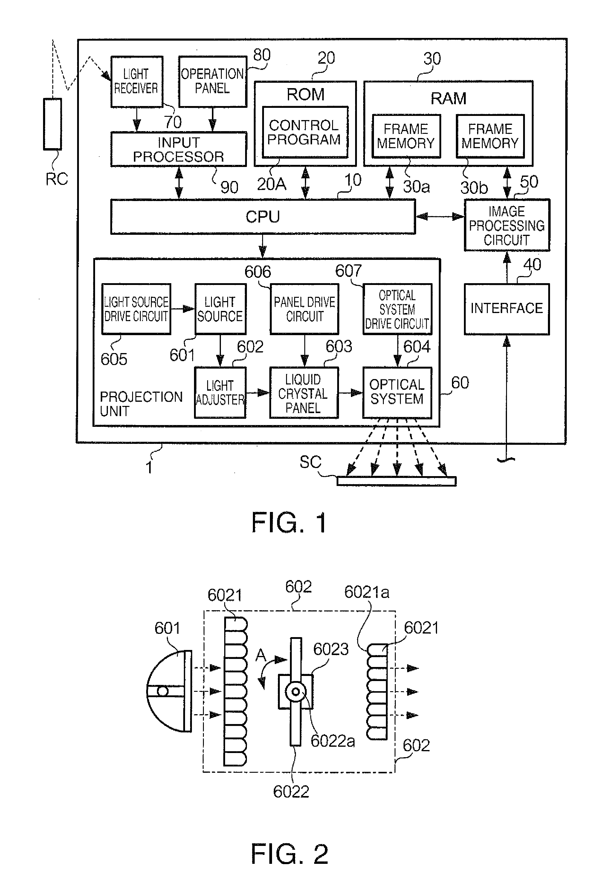
[0026]FIG. 1 is a block diagram showing the internal configuration of a projector 1 according to an embodiment of the invention. The projector 1 is an apparatus that projects an image on a screen SC. A controller RC is an apparatus for controlling the projector 1 wirelessly, for example, via an infrared communication. In other words, the controller RC is what is called a remote control. The screen SC is a flat surface on which an image projected from the projector 1 is displayed.

[0027]The projector 1 includes a CPU (central processing unit) 10, a ROM (read only memory) 20, a RAM (random access memory) 30, an IF (interface) 40, an image processing circuit 50, a projection unit 60, a light receiver 70, an operation panel 80, and an input processor 90. The CPU 10 is a control device that controls the components of the projector 1 by executing a control program 20A. The ROM 20 is a nonvolatile storage device that stores various kinds of programs and data. The ROM 20 stores the control p...


PUM


Abstract

An image processing apparatus includes a signal generation section that generates a drive signal to drive a light attenuation member that attenuates light radiated from a light source based on a difference between first transmittance and second transmittance, the first transmittance being a target value calculated based on image data and the second transmittance being detected based on the position of the light attenuation member, an expansion factor calculation section that calculates an expansion factor based on the first transmittance and the second transmittance, an expansion section that expands the range of the distribution of luminance values in the image data based on the expansion factor calculated by the expansion factor calculation section, and an output section that outputs the image data expanded by the expansion section to a driver that drives a light modulator that modulates light incident thereon.

Description

[0001]The entire disclosure of Japanese Patent Application No. 2013-059567, filed Mar. 22, 2013, is expressly incorporated by reference herein.BACKGROUND[0002]1. Technical Field[0003]The present invention relates to an image processing apparatus, a projector, and an image processing method.[0004]2. Related Art[0005]In an image processing apparatus, there is a known technology for improving the contrast of an image by carrying out the following processes combined with each other: the process of adjusting the amount of light radiated from a light source; and the process of expanding the range of the distribution of luminance values contained in image data. JP-A-2004-361703 describes a technology for adjusting the amount of light radiated from a light source by rotating a light attenuation plate with a stepper motor. JP-A-2004-361703 further describes a technology for expanding the range of the distribution of luminance values in image data by multiplying an image signal by an expansio...

Claims


Application Information

Patent Timeline
Patent Type & Authority Patents(United States)
IPC IPC(8): G03B21/20H04N9/31H04N5/20G09G3/34G09G3/36G09G3/00
CPCH04N5/20H04N9/3155H04N9/3182G09G3/3406G03B21/2053G09G3/002G09G3/3611G09G2320/0646G09G2360/16
Inventor NOBORI, TATSUHIKOHAYASHI, DAISUKEMOCHIZUKI, HIROTAKA
Owner SEIKO EPSON CORP
Why Eureka
Try Eureka