Gear spindle and rolling mill provided with same

a technology of gear spindles and rolling mills, which is applied in the direction of gearing, couplings, hoisting equipment, etc., can solve the problems of poor strip shape, easy breakage of gear spindles, and wear of their surfaces, so as to widen the load distributing range, and improve the allowable transmission torque

Active Publication Date: 2018-01-30
PRIMETALS TECHNOLOGIES JAPAN LTD
View PDF17 Cites 3 Cited by
  • Summary
  • Abstract
  • Description
  • Claims
  • Application Information

AI Technical Summary

Benefits of technology

[0046]According to the gear spindle of the first invention, 1200 [mm]≦Cr≦4000 [mm] is a range with which improvement in allowable transmission torque can be expected and which is practically usable. By setting the crown radius Cr within this range, the allowable transmission torque can be improved without any possibility of breakage at the neck portion of the spindle inner tube. Increasing the crown radius Cr widens the load distributing range at each tooth root and thereby improves the tooth root strength. Specifically, widening the load distributing range at each tooth root improves the tooth root strength, which in turn improves the spindle strength (surface pressure, bending, PV value). Thus, the spindle inclination angle does not need to be reduced more than necessary, and the spindle length can be shortened. Accordingly, a small-diameter and high-speed-rotation spindle can be realized. Note that increasing the crown radius Cr beyond the above range reduces the neck diameter d of the neck portion and increases the torsional stress in the neck portion. Consequently, excessively large load will be applied to the neck portion of the spindle inner tube.
[0047]According to the gear spindle of the second invention, B≦59.04×exp(0.0005×Cr) [mm] is a state where the tooth-root bending stress is not exceeding its allowable value. Accordingly, rotational power can be transmitted with large torque without any teeth being fractured by the tooth-root bending stress. Further, B≦32×Cr0.247 [mm] is a state the backlash amount is not exceeding its allowable value. Accordingly, rotational power can be transmitted with large torque without poor mesh due to excessive increase in backlash amount.
[0048]According to the gear spindle of the third invention, 1200 [mm]≦Cr≦4000 [mm] is a range with which improvement in allowable transmission torque can be expected and which is practically usable. By setting the crown radius Cr within this range, the allowable transmission torque can be improved without any possibility of breakage at the neck portion of the spindle inner rube. Note that increasing the crown radius Cr beyond the above range reduces the neck diameter d of the neck portion and increases the torsional stress in the neck portion. Hence, there will be a possibility of breakage at the neck portion of the spindle inner tube.
[0049]According to the gear spindle of the fourth invention, B≦18×exp (0.001×Cr) [mm] is a state where the tooth-root bending stress is not exceeding its allowable value. Accordingly, the gear spindle can handle high speed rotation and large transmission torque without any possibility of tooth fracture. Further, B≦19×Cr0.292 [mm] is a state the backlash amount is not exceeding its allowable value. Accordingly, the gear spindle can handle high speed rotation and large transmission torque without poor mesh due to excessive increase in backlash amount. Furthermore, margins for use such as machining errors and deterioration with time is not taken into consideration, without decreasing the allowable transmission torque of each tooth. Accordingly, the cost, weight, and size can be further reduced.
[0050]According to the gear spindle of the fifth invention, fine dimples are created in the tooth surfaces. By maintaining oil in the dimples, oil film shortage can be prevented. Thus, it is possible to prevent seizure of the tooth surfaces of the inner-tube gear portion and the outer-tube gear portion. Since the seizure of the tooth surfaces will not occur even in the case of transmitting large torque, the allowable transmission torque of the gear spindle can be further improved.
[0051]According to the gear spindle of the sixth invention, a manganese phosphate film is porous crystals. Thus, the film has an oil retaining ability and also has good initial conformability. Accordingly, the generation of frictional heat can be reduced, and the seizure of the tooth surfaces of the inner-tube gear portion and the outer-tube gear portion can be prevented. Since the seizure of the tooth surfaces will not occur even in the case of transmitting large torque, the allowable transmission torque of the gear spindle can be further improved.

Problems solved by technology

As the work rolls are used for rolling, their surfaces become worn due to the contact with the rolling target strips, and the surfaces are often polished with a polishing machine.
In the case of a rolling mill, its gear spindles, which are rotary bodies, may easily break due to the resonance.
Even if the resonance does not occur, the vibration is still transmitted to the rolling target strip and results in uneven strip thickness, a poor strip shape, and poor surface texture, which can cause a significant quality loss to the rolling target strip.
The functions required for gear spindles for high tensile strength steel rolling described above have a problem of interfering with other functions.
However, there is the problem in that a gear spindle for high tensile strength steel rolling is more likely to vibrate due to its small outer diameter, and also the vibration is even more likely to occur if the gear spindle length L is increased.
Thus, reducing the inclination angle θ is difficult co achieve with current techniques.

Method used


Image

  • Gear spindle and rolling mill provided with same
  • Gear spindle and rolling mill provided with same
  • Gear spindle and rolling mill provided with same

Examples


embodiment 1

[0067]A gear spindle and a rolling mill equipped with the same according to Embodiment 1 of the present invention will be described with reference to FIGS. 1 to 7.

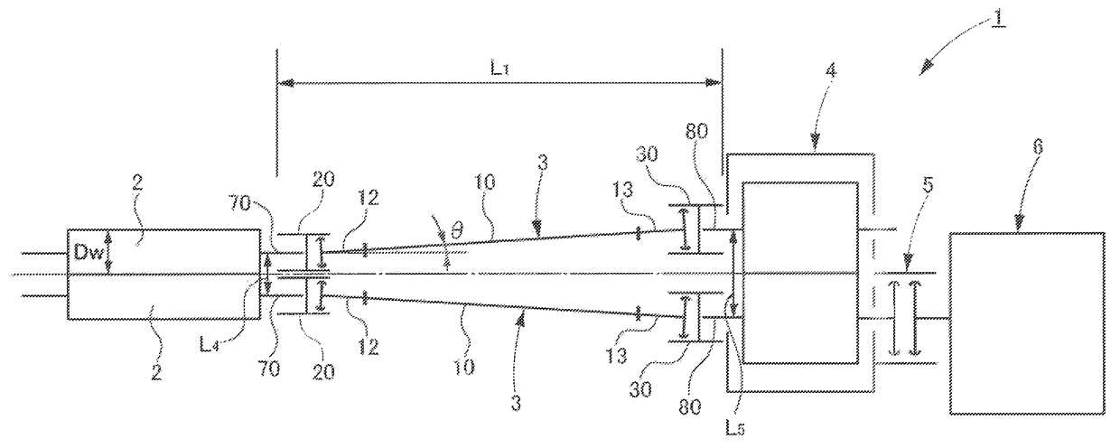
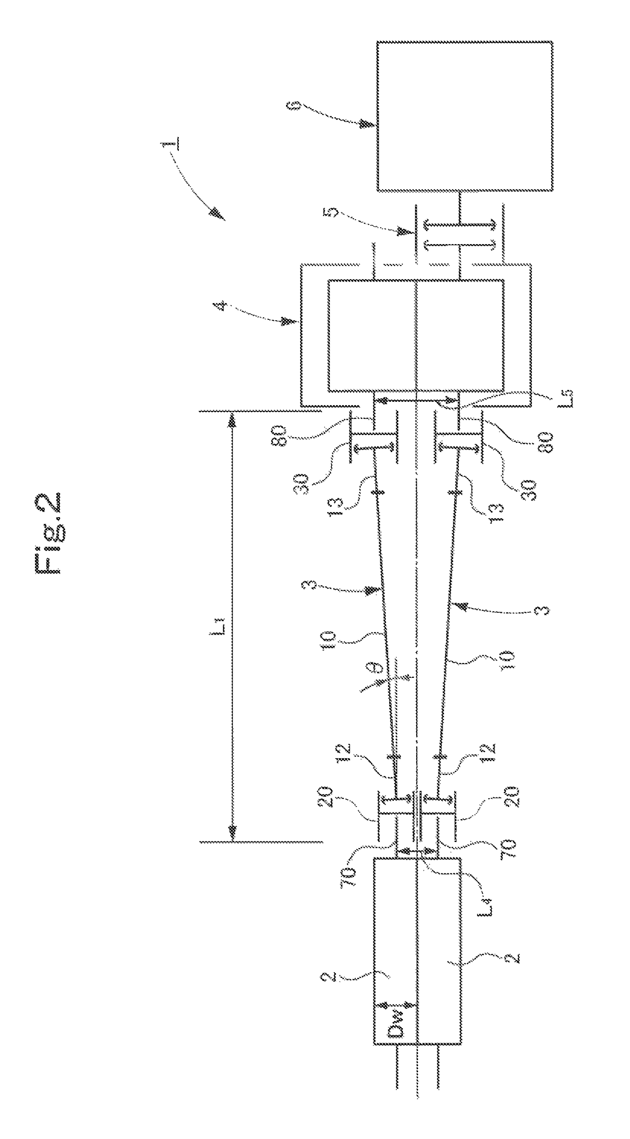
[0068]As shown in FIG. 2, a rolling mill 1 of this embodiment includes: a pair of upper and lower work rolls 2 for rolling a rolling target strip; a pair of upper and lower gear spindles 3 coupled to the pair of upper and lower work rolls 2, independently and respectively, and configured to transmit rotational power to the pair of upper and lower work rolls 2, independently and respectively; a transmission 4 coupled to the pair of upper and lower gear spindles 3 and configured to change the speed of rotational power to a predetermined rotational speed and distribute the changed rotational power to the pair of upper and lower gear spindles 3; a gear coupling 5 coupled to the transmission 4 and configured to transmit rotational power to the transmission 4; and an electric motor S coupled to the gear coupling 5 and configured...

embodiment 2

[0155]In this embodiment, the formula (3) for the facewidth B2 and the formula (6) for the facewidth B3, each representing a range within which the facewidth B is set with respect to the crown radius Cr, are calculations based on a setting where the. minimum necessary facewidth B with which tooth fracture due to edge contact at the tooth ends 44 will not occur does not take into consideration the maximum unexpected load during operation and the like (a setting where 20 [mm] is not secured from each tooth end 44 in the minimum necessary facewidth B).

[0156]This maximum unexpected load during operation is dependent on the specifications of the rolling target strip, operating conditions, and the like and differs from one case to another. In other words, the facewidth B can be further reduced to the minimum necessary in a case where the maximum unexpected load does not need to be taken into consideration.

[0157]Thus, as shown in FIG. 7, instead of the facewidth B2, a facewidth B20 is set ...


PUM

PropertyMeasurementUnit
inclination angleaaaaaaaaaa
outer diameteraaaaaaaaaa

Abstract

A gear spindle (3) obtained by inclining the axis of a spindle inner tube (10) provided at one end with an external cog inner tube gear section (40) at 0.6 degrees to 1.6 degrees with respect to the axis of a spindle outer tube (20) provided with an internal cog outer tube gear section (50) that meshes the inner tube gear section (40). On the teeth of the inner tube gear section (40) having a face width (B), a crowning of radius (Cr) is provided so that the center in the face width direction is expanded and both tooth ends are thin. The face width (B) and the crowning radius (Cr) are set within an area that is enclosed by graphs of (Cr)=1200 [mm], (Cr)=4000 [mm], (B)=0.0272×(Cr)+28 [mm], (B)=59.04×exp (0.0005×(Cr)) [mm], and (B)=32×(Cr)0.274 [mm].

Description

TECHNICAL FIELD[0001]The present invention relates to a gear spindle and a rolling mill equipped with the same.BACKGROUND ART[0002]The work rolls of rolling mills are rotationally driven by an electric motor. The rotationally driving power is transmitted from the electric motor to the pair of upper and lower work rolls through a transmission having a power distributing function and through a pair of spindles.[0003]The type of spindles used varies depending on how its use, such as rolling conditions. For example, UJ spindles (Universal Joint, also called propeller shafts) are used in rolling mills for rolling materials with normal hardness, and gear spindles are used in hard material rolling mills for rolling materials with relatively high hardness (e.g. a material with a 40%-reduction deformation resistance value of 70 [kg / mm2]).[0004]High tensile strength steels which are even harder materials (also called high tensile materials, e.g. a material with a 40%-reduction deformation res...

Claims


Application Information

Patent Timeline
Patent Type & Authority Patents(United States)
IPC IPC(8): F16H37/04F16H55/08F16H55/06F16D3/18B21B35/14
CPCB21B35/14F16D3/185
Inventor YAMAMOTO, KENJI
Owner PRIMETALS TECHNOLOGIES JAPAN LTD
Why Eureka
Try Eureka