Mouthpiece anti-loose device and anti-loose method

A horn mouth and anti-loosening technology, applied in the direction of electrical components, etc., can solve the problems of loosening the horn mouth, no anti-loosening protection of the horn mouth, explosion of electrical equipment, etc. The effect of lock failure

Active Publication Date: 2014-08-27
SHANXI QUANAN NEW TECH DEV CO LTD
View PDF8 Cites 1 Cited by
  • Summary
  • Abstract
  • Description
  • Claims
  • Application Information

AI Technical Summary

Problems solved by technology

The mine switch has a bell mouth for the power supply to enter and exit, which is connected to the switch wiring cavity. The bell mouth belongs to GB3836.1-2010 Explosive gas atmosphere uses electrical equipment 3.17 compression element, which is a sealing ring of the cable lead-in device. Components that apply pressure to ensure their effective functions, and the horn mouth (especially the spiral horn mouth) is easy to be loosened by hand or with ordinary tools intentionally or unintentionally, causing electrical equipment to "explode"
At present, there are almost no studies and reports on the anti-loosening protection of bell mouths, especially the bell mouths of coal mine electrical equipment at home and abroad.

Method used


Image

  • Mouthpiece anti-loose device and anti-loose method
  • Mouthpiece anti-loose device and anti-loose method
  • Mouthpiece anti-loose device and anti-loose method

Examples


Embodiment 1

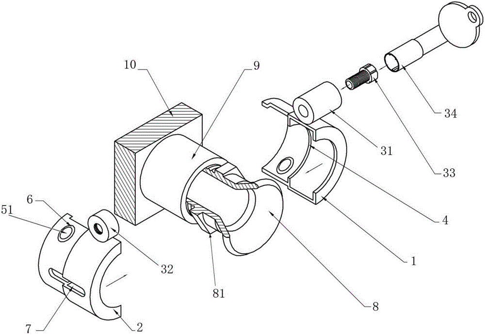
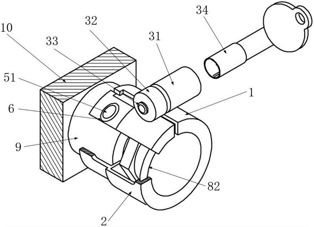
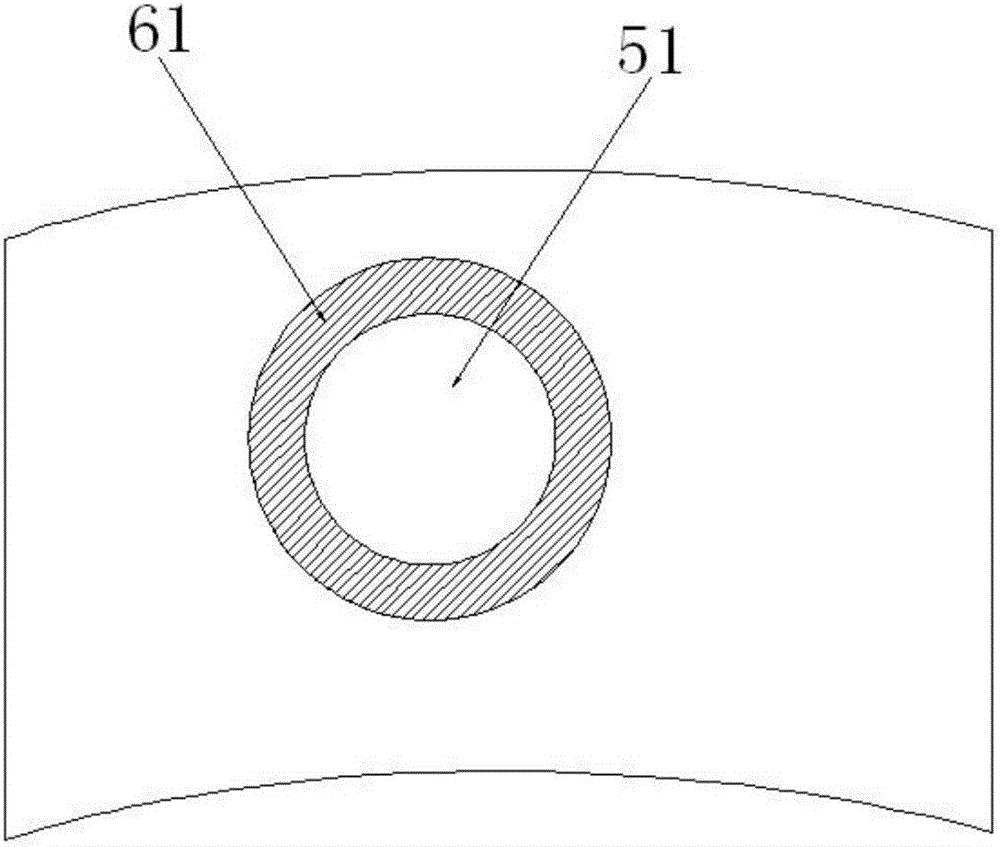
[0031] As shown in FIG. 3 , a through hole 51 is opened on the inner wall connecting the first lock body 1 and the second lock body 2 with the joint 9 , and then the prepared anti-loosening pad 6 is installed in the through hole 51 . In this case, it is preferable to set the anti-loosening pad 6 as a washer 61 that matches the through hole 51, and the outer wall of the washer 61 is provided with a groove, which can be connected with the first lock body 1 and the second lock body around the through hole 51. The two lock bodies 2 are engaged and sealed.

[0032]In this embodiment, there are many options for the shape of the groove, such as U-shape, semi-U-shape, trapezoid, etc., all of which can perform the same function.

Embodiment 2

[0034] As shown in FIG. 4 , a blind hole 52 is opened on the inner wall connecting the first lock body 1 and the second lock body 2 with the joint 9 , and then the prepared anti-loosening pad 6 is installed in the blind hole 52 . In this case, the anti-loosening pad 6 can be configured as a spacer 62 matching the blind hole 52 , which has a protrusion protruding relative to the inner wall surfaces of the first lock body 1 and the second lock body 2 . There are many options for the shape of the protruding part, such as a column that is integrated with the spacer 62 , or a sheet that fits and extends around the inner walls of the first lock body 1 and the second lock body 2 .

[0035] The anti-loosening pad 6 of the present invention can be made of various materials, preferably made of one or more of rubber, nylon or other anti-friction materials, which can avoid the trouble of using (pasting) friction materials such as rubber in the traditional technology. The disadvantage of t...


PUM


Abstract

A horn nozzle anti-loosening apparatus and an anti-loosening method. The apparatus comprises a first lock body (1) and a second lock body (2) with semicircular cylindrical inner walls; locking components arranged on the first lock body (1) and the second lock body (2); locking rings (4) arranged on the inner walls of the first lock body (1) and the second lock body (2); a communicating joint (9) that matches the inner walls of the first lock body (1) and the second lock body (2); a horn nozzle (8) connected to the communicating joint (9); and anti-slip pads (6) installed on the inner walls of the first lock body (1) and the second lock body (2). An installation slot is formed between a front end of the communicating joint (9) and a horn side wall (82); or a bump (81) is arranged on the horn mouth, and an installation slot is formed between the bump and the horn side wall (82) or the front end of the communicating joint (9). The installation slot is used for clamping the lock rings (4). The anti-loosening method corresponds to the horn nozzle anti-loosening apparatus. The horn nozzle anti-loosening method and the apparatus are convenient and useful, and can effectively prevent an electrical device losing its explosion-resistance protection due to a horn nozzle being loosened by hand or by means of a non-specific tool.

Description

technical field [0001] The invention relates to the technical field of electrical equipment protection, in particular to a bell mouth anti-loosening device and an anti-loosening method for electrical equipment. Background technique [0002] Electric spark ranks first among the many factors that ignite the ignition source of coal mine gas explosion, about 70%. Preventing "detonation" from generating electric sparks is particularly important for preventing gas explosions. The mine switch has a bell mouth for power supply in and out, which is connected to the switch wiring cavity. The bell mouth belongs to GB3836.1-2010 Explosive gas atmosphere uses electrical equipment 3.17 compression element, which is a sealing ring for the cable entry device Components that apply pressure to ensure their effective functions, such as bell mouths (especially screw-type bell mouths) are easy to be loosened by hand or with ordinary tools intentionally or unintentionally, resulting in "explosio...

Claims


Application Information

Patent Timeline
Patent Type & Authority Applications(China)
IPC IPC(8): H02G3/04
CPCH02G3/04H02G3/22
Inventor 郭春平
Owner SHANXI QUANAN NEW TECH DEV CO LTD
Why Eureka
Try Eureka