Light path planning method

A path planning and optical path technology, applied in multiplexing system selection devices, digital transmission systems, data exchange networks, etc., can solve the problems of time-consuming and laborious, easy to miss the optimal path, etc., to avoid missing the better path Effect

Active Publication Date: 2014-08-27
STATE GRID CORP OF CHINA +2
View PDF7 Cites 8 Cited by
  • Summary
  • Abstract
  • Description
  • Claims
  • Application Information

AI Technical Summary

Problems solved by technology

[0003] In the past, optical path selection was usually planned by manually consulting optical cable data and network topology, which was time-consuming and laborious, and it was easy to miss the optimal path.

Method used


Image

  • Light path planning method

Examples


Embodiment 1

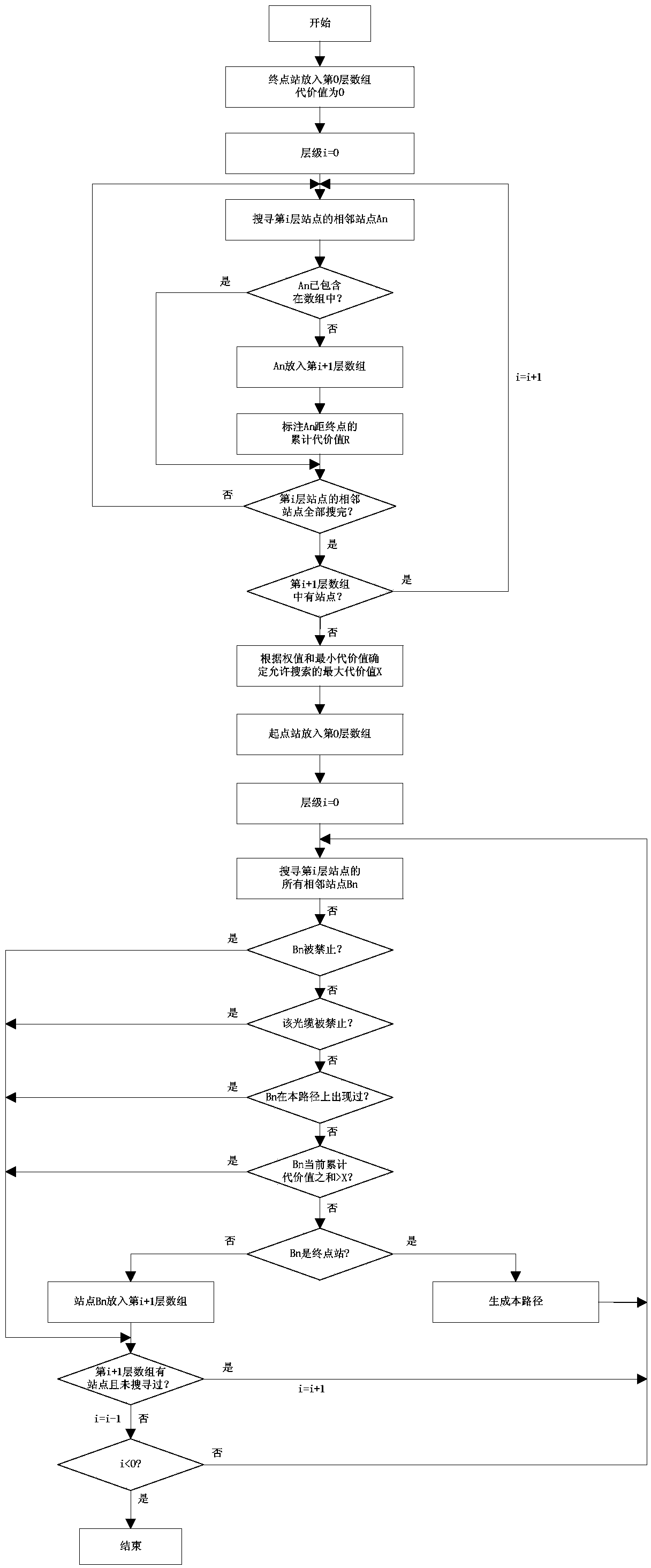
[0024] Embodiment one: as attached figure 1 An optical path planning method is shown, which is used to plan and select an appropriate path between certain two nodes in an optical fiber communication network composed of several optical cables and nodes on them.

[0025] The method specifically includes the following steps:

[0026] 1. Determine the starting and ending points:

[0027] Determine the starting point and the ending point of the path to be planned in the optical fiber communication network.

[0028] 2. Flood layer by layer and identify the cost value:

[0029] First define the end point as layer 0 node A 0 , its cost value is 0, and then the node A at layer 0 0 Flood outward, looking for node A with layer 0 0 directly adjacent nodes and defined as layer 1 node A 1 . At each layer 1 node A 1 mark the cost value of the optical path formed by the optical cable between it and the terminal. The cost value is based on the node A 1 The parameters of the optical c...


PUM


Abstract

The invention relates to a light path planning method. The light path planning method includes the steps that 1 a starting point and an end point of a path are determined in an optical fiber communication network; 2 the end point is defined as a 0th layer of node, a previous layer of nodes conducts flooding layer by layer to look for a next layer of nodes, and cost values of accumulative light paths between the found nodes and the end point are marked at the positions of the found nodes; 3 the light path with the minimum cost value between the starting point and the end point and the minimum cost value M of the light path are looked for; 4 a cost permission value N is set, and a maximum allowable cost value X is calculated according to the minimum cost value M and the cost permission value N, wherein X is equal to M plus N; 5 the starting point is defined as the 0th layer of node again, the previous layer of nodes conducts flooding layer by layer to look for the next layer of nodes, whether the sum of the cost value between each found node and the starting point and the cost value between the found node and the end point is less than or equal to the maximum allowable cost value X, if yes, the node and the light path where the node is located meet requirements, and therefore a suitable path is obtained. According to the method, a suitable path between two nodes can be looked for rapidly and accurately.

Description

technical field [0001] The invention relates to a method for planning a suitable optical path between two points in a fiber optic communication network. Background technique [0002] After decades of development, the power communication network has become a modern communication network with diversified communication methods, complex structure and perfect functions. Especially in the past ten years, with the popularization of optical fiber communication, the scale of the communication network has undergone tremendous changes in the number of nodes and optical cables. The optical fiber network has been distributed in a spider web, which makes the communication between two communication node devices There are many options for the optical path to choose from. [0003] In the past, optical path selection was usually planned by manually consulting optical cable data and network topology, which was time-consuming and laborious, and it was easy to miss the optimal path. Therefore,...

Claims


Application Information

Patent Timeline
Patent Type & Authority Applications(China)
IPC IPC(8): H04Q11/00H04L12/721
Inventor 程晓翀
Owner STATE GRID CORP OF CHINA
Why Eureka
Try Eureka