Door for a thrust reverser with doors

A thrust reverser and door-type technology, applied in high-efficiency propulsion technology, jet propulsion devices, machines/engines, etc., can solve the problems of thrust reverser performance degradation, spoiler geometric structure, vibration, etc., to achieve Effects of weight reduction and easy assembly

Inactive Publication Date: 2014-08-27
AIRCELLE
View PDF7 Cites 3 Cited by
  • Summary
  • Abstract
  • Description
  • Claims
  • Application Information

AI Technical Summary

Problems solved by technology

[0013] Another disadvantage of this solution is related to the geometry of the spoiler
In fact, such a spoiler according to the state of the art deforms under load and vib

Method used


Image

  • Door for a thrust reverser with doors
  • Door for a thrust reverser with doors
  • Door for a thrust reverser with doors

Examples


Embodiment Construction

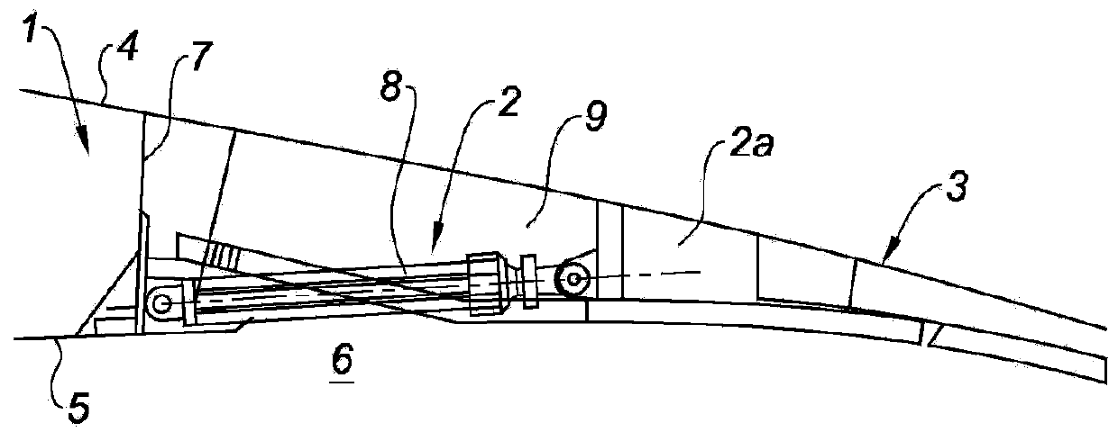
[0052] figure 1 A known example of a portal thrust reverser equipped with a deflecting spoiler is shown.

[0053] This type of thrust reverser comprises three main parts, namely a fixed part 1 upstream of the extension of the outer wall of the turbojet air flow passage, a movable part 2 and a rear fixed collar 3 .

[0054] The fixed part 1 comprises an outer panel 4 and an inner panel 5 of the nacelle, the inner panel 5 constituting the outer panel of an airflow flow path 6 .

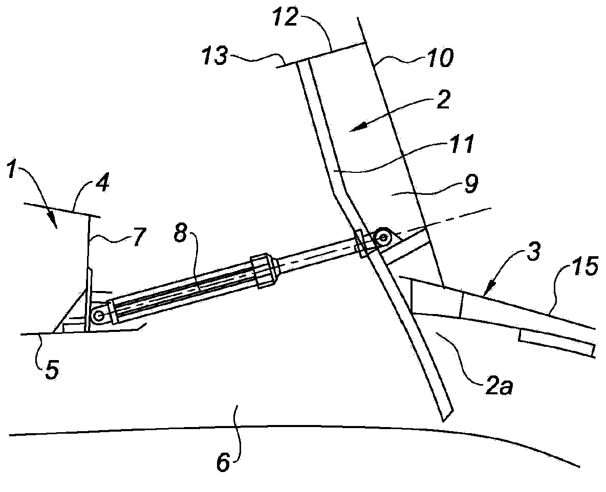
[0055] The outer 4 and inner 5 panels of the fixed part 1 are connected by a front frame 7 which also ensures the support of the means for controlling the movable part 2 , constituted in this example by jacks 8 . The movable part 2 is broken down into one or several generally movable members called doors 9 .

[0056] Each door 9 is pivotally mounted in such a way as to be able to move under the action of the control device 8 between the open position and the position ensuring structural continuity bet...


PUM


Abstract

A door for a door-type thrust reverser is pivotally mounted on a stationary structure of a thrust reverser. The door includes an inner surface integrated to a flow path of an air flow generated by a turbojet engine, an outer surface providing an outer aerodynamic continuity of a nacelle equipped with the thrust reverser, a spoiler to deflect the air flow disposed at an upstream end of the door, and an actuator actuating the spoiler. The spoiler is movably mounted, in rotation around a rotation axis substantially perpendicular to a front frame of the door, between a retracted and a deployed position. In particular, the actuator includes a first rod connected to the spoiler, a second rod connected to the first rod and the front frame, and a third rod connected to the first and second rods as well as to the spoiler.

Description

technical field [0001] The invention relates to a door for a thrust reverser of the portal type, as well as such a thrust reverser and a nacelle equipped with such a thrust reverser. Background technique [0002] The function of the thrust reverser during landing of the aircraft is to increase the braking capability of the aircraft by redirecting at least a part of the thrust generated by the turbojet engine forward. During this phase, the thrust reverser blocks the gas nozzles and directs the jets of the engine jets towards the front of the nacelle, creating reverse thrust accompanied by braking of the aircraft's wheels. The means used to achieve this airflow redirection vary according to the type of thrust reverser. [0003] The structure of the thrust reverser consists of movable cowls that move between a deployed position on the one hand, and a retracted position on the other hand, in which they open in the nacelle for diverting the airflow channels, in said retracted ...

Claims


Application Information

Patent Timeline
IPC IPC(8): F02K1/62F02K1/70
CPCF05D2260/52F05D2260/50F02K1/62F02K1/566F02K1/70Y02T50/60F02K1/605F02K1/60F02K1/763
Inventor 尼古拉斯·德泽斯特泽维尔·埃尔特吕克·卡尔内
Owner AIRCELLE
Why Eureka
Try Eureka