Component Imaging Device, And Component Mounting Device Equipped With Component Imaging Device

A camera device and camera unit technology, which is applied in the field of component mounting devices and component camera devices, and can solve problems such as difficult to capture projected images of components, difficult to capture and maintain image quality, etc.

Active Publication Date: 2014-08-27
YAMAHA MOTOR CO LTD
View PDF6 Cites 7 Cited by
  • Summary
  • Abstract
  • Description
  • Claims
  • Application Information

AI Technical Summary

Problems solved by technology

[0004] However, if a plurality of heads are arranged in two rows before and after, it is difficult to take a projected image of the elements because the holding elements of the heads arranged in front and behind overlap each other.
[0005] In such a case, the holding elements of the heads arranged in two rows

Method used


Image

  • Component Imaging Device, And Component Mounting Device Equipped With Component Imaging Device
  • Component Imaging Device, And Component Mounting Device Equipped With Component Imaging Device
  • Component Imaging Device, And Component Mounting Device Equipped With Component Imaging Device

Examples


no. 1 Embodiment approach

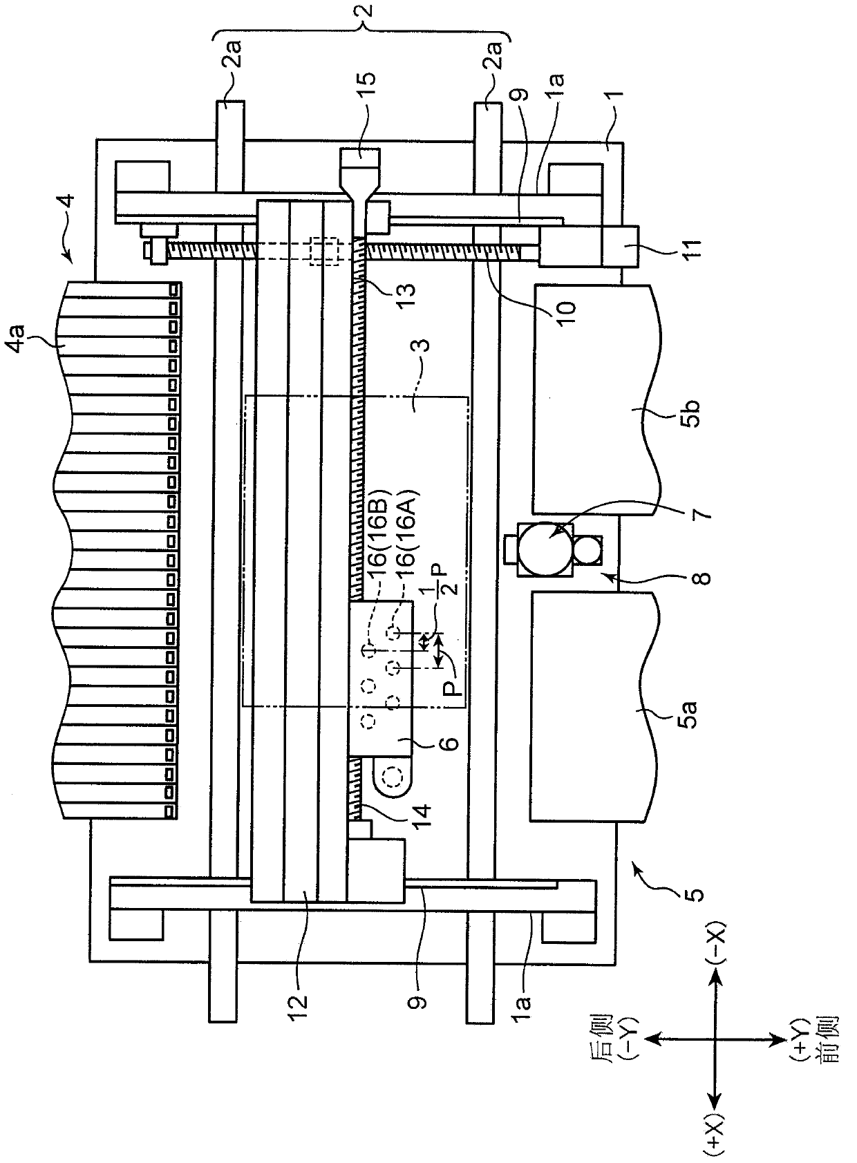
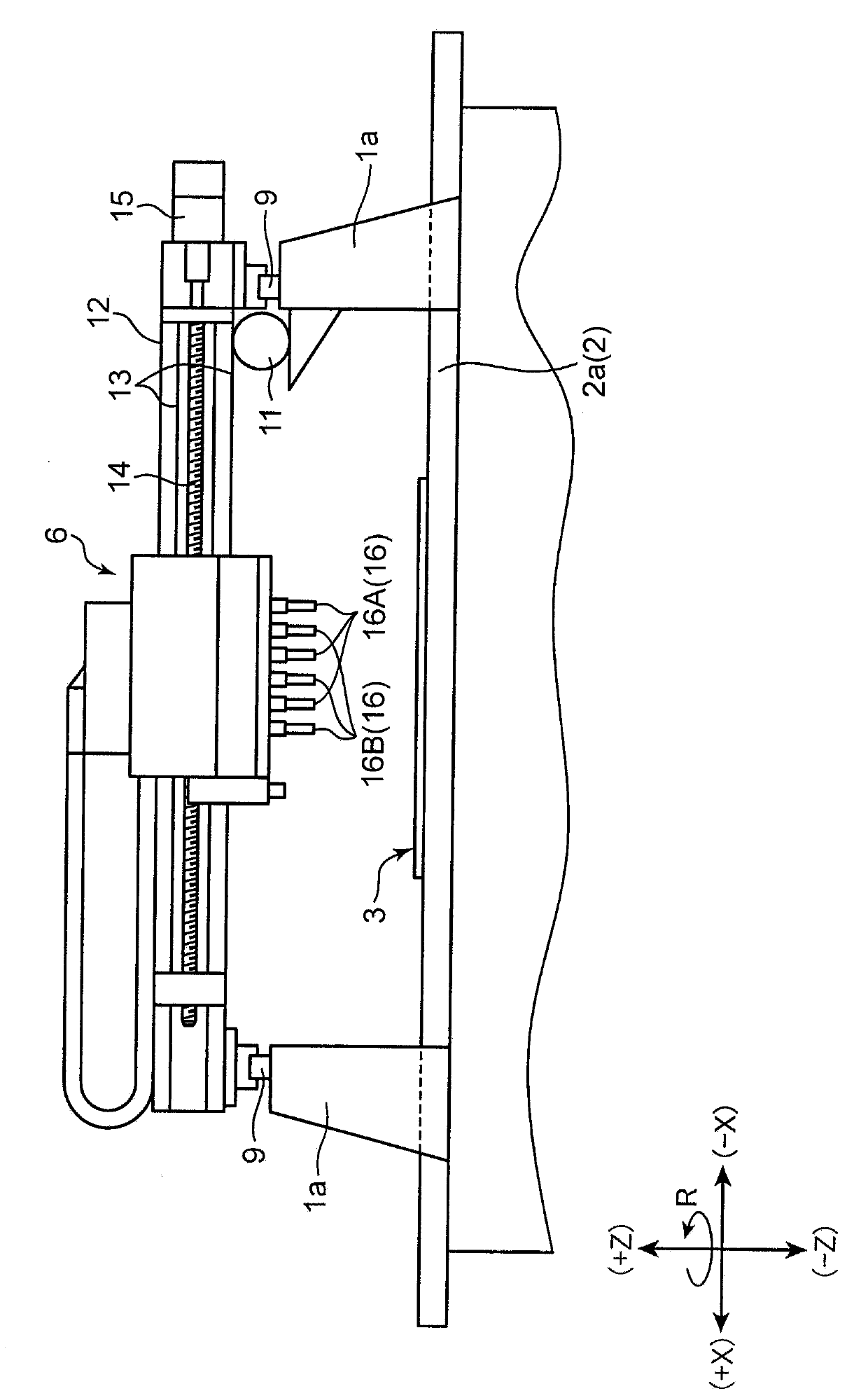
[0030] figure 1 and figure 2 The component mounting apparatus (component mounting apparatus equipped with the component imaging device of this invention) which concerns on this invention is shown schematically. figure 1 for top view, figure 2 It is a front view and schematically shows each component mounting device. exist figure 1 , figure 2 In the drawings described below, XYZ rectangular coordinate axes are shown to clarify the directional relationship.

[0031] The component mounting apparatus includes: a base 1; a substrate transport mechanism 2 provided on the base 1 and transporting a substrate 3 such as a printed wiring board (PWB) in the X direction; component supply parts 4 and 5; With the head unit 6 ; a head unit drive mechanism that drives the head unit 6 ; a component imaging unit for recognizing a holding component of the head unit 6 , and the like.

[0032] The substrate transport mechanism 2 includes a pair of transport belts 2 a , 2 a for transporting...

no. 2 Embodiment approach

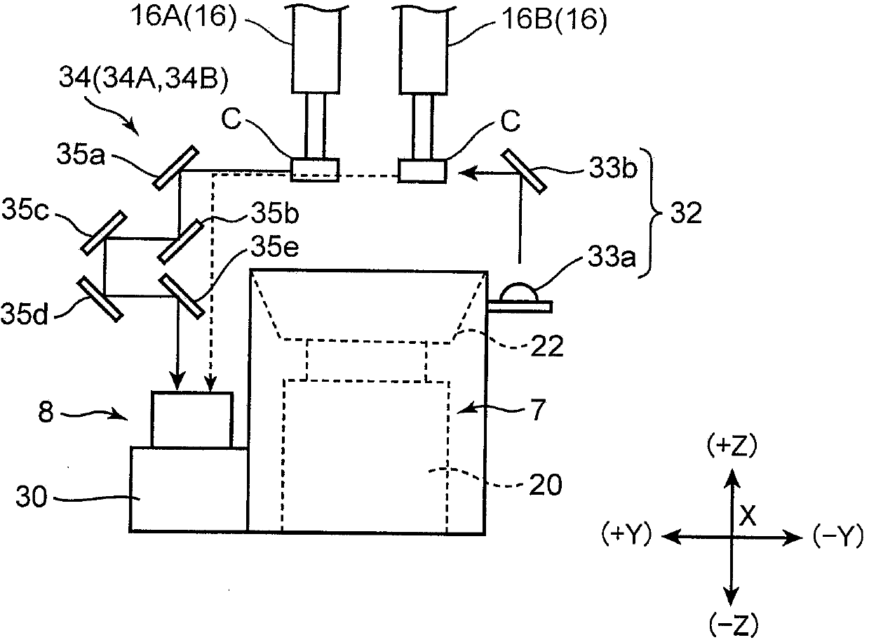
[0061] Figure 7 and Figure 8 The component imaging unit in the component mounting apparatus which concerns on 2nd Embodiment is shown schematically. The configuration of the second component imaging unit 8 of this component mounting device differs from the first embodiment in the following points, and other configurations are basically common to the component mounting device of the first embodiment. Therefore, in the following description, the same reference numerals will be attached to the parts common to the first embodiment, and the description will be omitted, and the differences from the first embodiment will be mainly described in detail.

[0062] The illuminating unit 32 of the second element imaging unit 8 according to the second embodiment includes: a first light source 333a for irradiating illumination light with a first wavelength; and a second light source 333b for irradiating illumination with a second wavelength different from the first wavelength. Light. Th...

no. 3 Embodiment approach

[0071] Figure 9 and Figure 10 The component imaging unit in the component mounting apparatus which concerns on 3rd Embodiment is shown schematically. The structure of the second component imaging unit 8 of the structure of this component mounting device differs from the first embodiment in the following points, and the other structures are basically common to the component mounting device of the first embodiment. Therefore, in the following description, the same reference numerals will be attached to the parts common to the first embodiment, and the description will be omitted, and the differences from the first embodiment will be mainly described in detail.

[0072] The second component imaging unit 8 of this third embodiment has a camera 30 including a CCD line sensor (referred to as a line sensor 31 ). The camera 30 is installed in such a manner that the imaging elements are arranged in the Y direction, and sequentially captures the projection image of one line of the c...


PUM


Abstract

This component imaging device is equipped with: a head unit that has a first row of heads and a second row of heads, each row including multiple heads; an imaging unit for capturing images of components held by the respective heads; a moving means for moving the head unit relative to the imaging unit; and an imagining control means. The imaging unit is equipped with an image sensor and an optical system. The optical system includes a first light-guiding unit for guiding light from a component held by a head of the first row to the image sensor and a second light-guiding unit for guiding light from a component held by a head of the second row to the image sensor. The light path length of the first light-guiding unit is set such that a focused image can be obtained of the component held by head of the first row, and the light path length of the second light-guiding unit is set such that a focused image can be obtained of the component held by the head of the second row. The imaging control means controls the height positions of the respective rows of heads and exposure timing of the image sensor.

Description

technical field [0001] The present invention relates to a component imaging device that captures a component held on a head from the side thereof, and a component mounting device including the component imaging device. Background technique [0002] Conventionally, there is known a component mounting device in which a component is taken out from a component supply unit by a component mounting head and mounted at a mounting position on a board. As such a component mounting device, there is known a device that recognizes the component holding state of the head in advance by photographing the component held on the head from the side of the component before mounting the component on the board. For example, the component mounting device disclosed in Patent Document 1 includes a head unit, and a plurality of mounting heads are mounted on the head unit in a line. The illuminating device irradiates illuminating light from the side, and a camera is fixedly mounted on a supporting mem...

Claims


Application Information

Patent Timeline
IPC IPC(8): H05K13/08
CPCH05K13/0452H05K13/0413G01N21/95684H05K13/041H05K13/0812H04N23/55H04N23/56H04N23/54H04N23/45H04N23/741H04N23/75
Inventor 大西正志
Owner YAMAHA MOTOR CO LTD
Why Eureka
Try Eureka