

Takeoff and landing control device for rotor unmanned aerial vehicle and control method thereof
A technology of unmanned rotor and control device, which is applied in the directions of unmanned aerial vehicle, launch/drag transmission device, motor vehicle, etc., can solve the problem of high terrain requirements, and achieve low terrain correlation, convenient landing and simple structure. Effect
- Summary
- Abstract
- Description
- Claims
- Application Information
AI Technical Summary
Problems solved by technology
Method used
Image

Examples
Embodiment 1
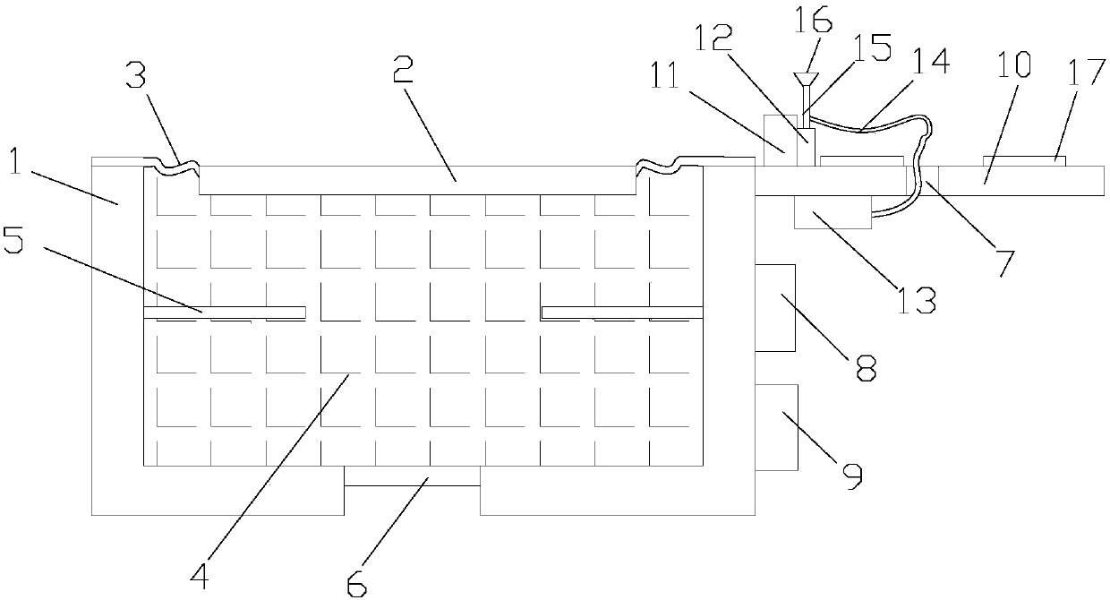
[0025] Such as figure 1 As shown, a landing control device for a rotor UAV includes a base 1 and a floating board take-off platform 2, the base 1 is provided with a storage tank (not shown), and the base 1 and the floating board take-off platform 2 A rubber connecting piece 3 is arranged between them, and the base 1 and the floating board take-off platform 2 are bonded with the rubber connecting piece 3, and the floating board taking-off platform 2 and the rubber connecting piece 3 are arranged to cover the notch of the storage tank, The storage tank is filled with liquid metal 4, the storage tank is provided with an electric heating iron 5 and a semiconductor refrigeration sheet 6, and the side of the base 1 is provided with a PLC 8, a battery box 9 and a landing plate 10, and the landing plate 10 is provided with a detection device 11 and an ejection mechanism 12, an electric wire take-up 13 is provided under the falling plate 10, a wire hole 7 is provided in the middle of t...
Embodiment 2
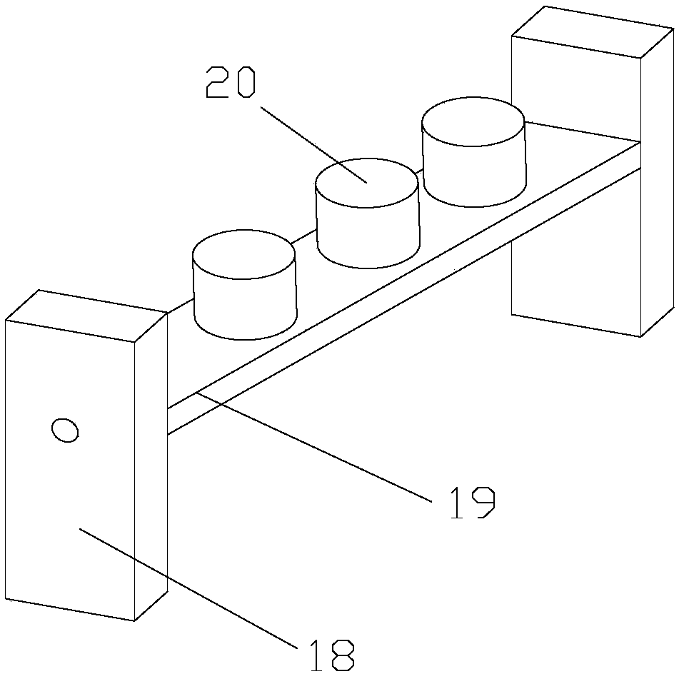
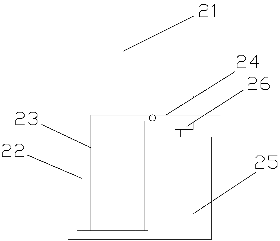
[0028] Such as Figure 1-4As shown, a landing control device for a rotor UAV includes a base 1 and a floating board take-off platform 2, the base 1 is provided with a storage tank (not shown), and the base 1 and the floating board take-off platform 2 A rubber connecting piece 3 is arranged between them, and the base 1 and the floating board take-off platform 2 are bonded with the rubber connecting piece 3, and the floating board taking-off platform 2 and the rubber connecting piece 3 are arranged to cover the notch of the storage tank, The storage tank is filled with liquid metal 4, the storage tank is provided with an electric heating iron 5 and a semiconductor refrigeration sheet 6, and the side of the base 1 is provided with a PLC 8, a battery box 9 and a landing plate 10, and the landing plate 10 is provided with a detection device 11 and an ejection mechanism 12, an electric wire take-up 13 is provided under the falling plate 10, a wire hole 7 is provided in the middle of...
PUM
 Abstract
Description
Claims
Application Information