LED chip and forming method thereof

A technology of LED chips and semiconductors, applied in semiconductor devices, electrical components, circuits, etc., can solve the problem of low luminous brightness of LED chips, and achieve the effects of improving luminous brightness, simple process, and widening the light emitting angle.

Active Publication Date: 2015-05-27
BYD SEMICON CO LTD
View PDF3 Cites 2 Cited by
  • Summary
  • Abstract
  • Description
  • Claims
  • Application Information

AI Technical Summary

Problems solved by technology

Low luminance

Method used


Image

  • LED chip and forming method thereof
  • LED chip and forming method thereof
  • LED chip and forming method thereof

Examples


Embodiment Construction

[0030] Embodiments of the present invention are described in detail below, examples of which are shown in the drawings, wherein the same or similar reference numerals designate the same or similar elements or elements having the same or similar functions throughout. The embodiments described below by referring to the figures are exemplary and are intended to explain the present invention and should not be construed as limiting the present invention.

[0031] In describing the present invention, it should be understood that the terms "center", "longitudinal", "transverse", "length", "width", "thickness", "upper", "lower", "front", " Orientation or position indicated by "back", "left", "right", "vertical", "horizontal", "top", "bottom", "inner", "outer", "clockwise", "counterclockwise", etc. The relationship is based on the orientation or positional relationship shown in the drawings, and is only for the convenience of describing the present invention and simplifying the descrip...


PUM


Abstract

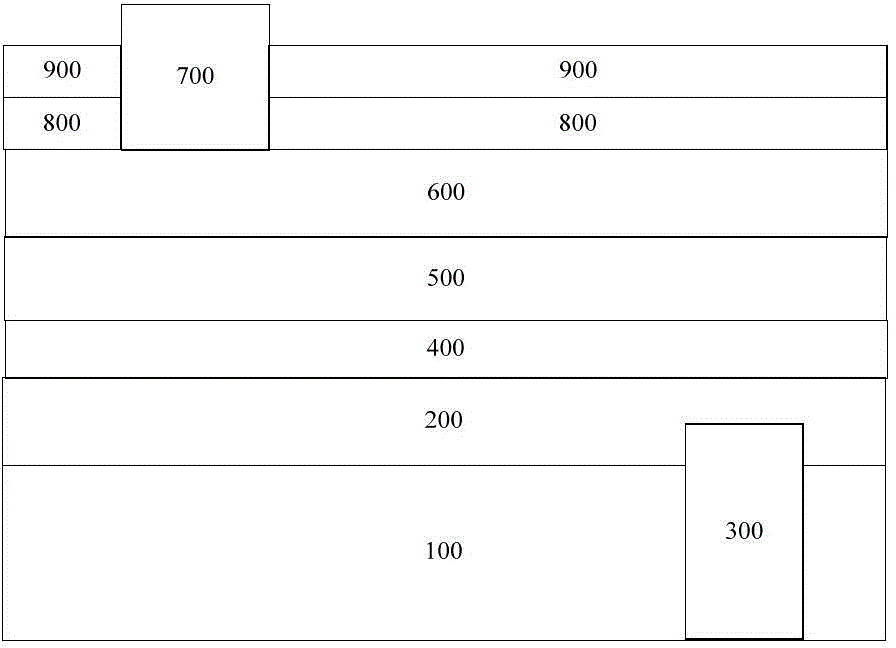
The invention discloses an LED chip and a forming method thereof. The LED chip comprises a substrate, a first doped semiconductor layer, a first electrode, multiple quantum wells, a second doped semiconductor layer, a current diffusion layer, a second electrode, a light-exiting transition layer and a passivation layer, wherein the first doped semiconductor layer is arranged on the substrate; the first electrode is in contact with the first doped semiconductor layer; the multiple quantum wells are arranged on the first doped semiconductor layer; the second doped semiconductor layer is arranged on the multiple quantum wells; the current diffusion layer is arranged on the second doped semiconductor layer; the second electrode is arranged on the first region of the current diffusion layer; the light-exiting transition layer is arranged on the second region of the current diffusion layer; the passivation layer is arranged on the light-exiting transition layer; the refractive indexes of the current diffusion layer, the light-exiting transition layer and the passivation layer are matched. The LED chip disclosed by the invention has the advantages of large light-exiting angle and the like.

Description

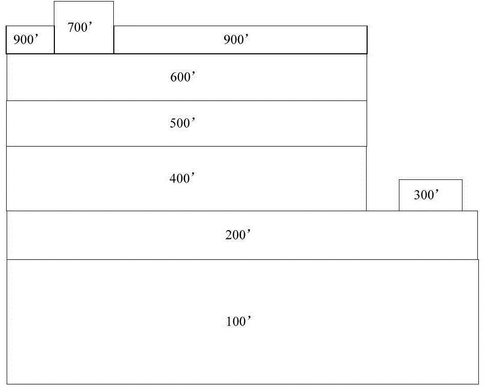
technical field [0001] The invention belongs to the technical field of semiconductors, and in particular relates to an LED chip and a forming method thereof. Background technique [0002] Due to the advantages of environmental protection, energy saving, and long life, LEDs are widely used. figure 1 It is a structural diagram of a horizontal structure LED chip in the prior art, including a substrate 100', a first doping type semiconductor layer 200', a quantum well 400', a second doping type semiconductor layer 500', and a current diffusion layer stacked in sequence. 600', and the first electrode 300', the second electrode 700' and the passivation layer 900' covering the top of the LED chip. Usually the current diffusion layer 600' is made of ITO material with a refractive index of 2.0; the passivation layer 900' is made of SiO 2 Material, refractive index 1.46. Due to the large difference in refractive index between the two, total reflection of light occurs on the light-e...

Claims


Application Information

Patent Timeline
IPC IPC(8): H01L33/00H01L33/58H01L33/02
CPCH01L33/02H01L33/44H01L33/58H01L2933/0025
Inventor 张杰彭遥
Owner BYD SEMICON CO LTD
Why Eureka
Try Eureka