Elevator and tail cord vibration damper equipped by the elevator

A technology of vibration damping device and elevator control device, applied in the directions of transportation and packaging, elevators, etc., can solve the problems of tail cable disconnection, large tail cable shaking, equipment failure, etc., and achieve the effect of convenient installation and operation.

Inactive Publication Date: 2014-09-03
HITACHI LTD
View PDF7 Cites 2 Cited by
  • Summary
  • Abstract
  • Description
  • Claims
  • Application Information

AI Technical Summary

Problems solved by technology

Therefore, when the tail cable shakes due to shaking of the building, etc., the tail cable is likely to collide with various equipment installed in the hoistway, which may cause equipment failure or disconnection of the tail cable.
Since the longer the length of the tail cable, the greater the swing of the tail cable, the above-mentioned problems are particularly likely to occur in elevators for high floors

Method used


Image

  • Elevator and tail cord vibration damper equipped by the elevator
  • Elevator and tail cord vibration damper equipped by the elevator
  • Elevator and tail cord vibration damper equipped by the elevator

Examples


no. 1 example

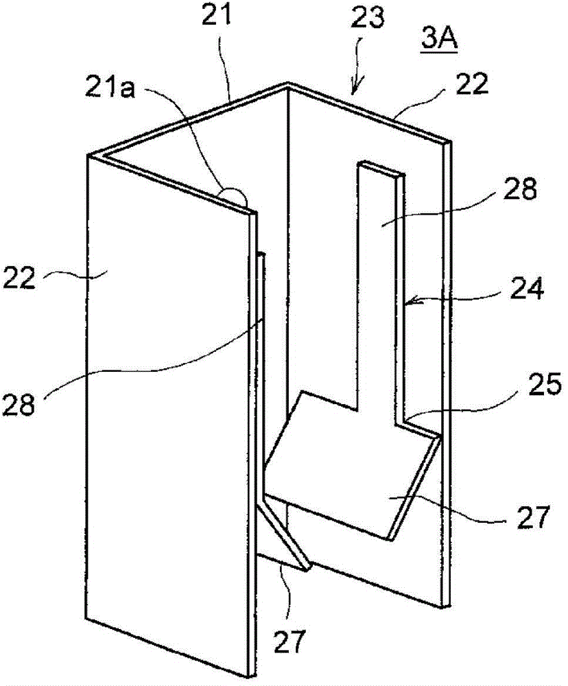
[0031] Such as Figure 3 to Figure 5 As shown, the tail cable damping device 3A according to the first embodiment is composed of a U-shaped holding frame 23, an L-shaped opening and closing member 24, and a disc spring 26, and the U-shaped holding frame 23 is composed of a base plate part 21 And two side plate parts 22 standing upright from the left and right sides of the base plate part 21 toward the same direction, the L-shaped opening and closing member 24 is installed on the inner surface of the side plate part 22, and the butterfly spring 26 is arranged on the side. Between the inner surface of the plate portion 22 and the bent portion 25 of the opening and closing member 24, the opening and closing member 24 is always biased in the opening direction.

[0032] One or more (in Figure 4 In the example shown above, there are two) bolt through holes 21a, and the holding frame 23 is fixed to the wall surface of the lifting passage 2 using unillustrated bolts passing through ...

no. 2 example

[0039] Such as Image 6 with Figure 7 As shown, the tail cable damping device 3B according to the second embodiment is composed of a substantially U-shaped holding frame 34, an arm-shaped opening and closing member 35, a coil spring 36, and a reinforcing member 37, and the substantially U-shaped holding The frame body 34 is composed of a base plate portion 31, two side plate portions 32 standing up in the same direction from the left and right sides of the base plate portion 31, and an opening and closing member bent outward from the front end of the side plate portion 32. fixed portion 33, arm-shaped opening and closing member 35 is rotatably mounted on the outer surface of opening and closing member setting portion 33, coil spring 36 is arranged between opening and closing member setting portion 33 and opening and closing member 35, Always keeping the opening and closing member 35 in a horizontal position, the reinforcing member 37 is provided outside the opening and closi...

no. 3 example

[0046] The tail cable damping device 3C involved in the third embodiment is as follows: Figure 8 As shown, it is composed of a U-shaped holding frame 43 and an opening and closing member 44. The U-shaped holding frame 43 consists of a base plate part 41 and two left and right sides of the base plate part 41 standing in the same direction. The side plate portion 42 is constituted, and the opening and closing member 44 is constituted by a V-shaped elastic plate whose one end is fixed to the outer surface of the side plate portion 42 .

[0047] A through hole 45 through which the front end side of the opening and closing member 44 can pass is opened in the side plate portion 42 , and one end of the opening and closing member 44 is fixed to an upper portion or a lower portion of the through hole 45 . In addition, an opening and closing member 44 bent into a V shape is protrudingly provided at an intermediate portion of both side plate portions 42 through a through hole 45 at a ce...


PUM


Abstract

The invention provides a tail cord vibration damper and an elevator equipped with the tail cord vibration damper. Arrangement space of the elevator is not required to be expanded for the tail cord vibration damper, installation operation of the elevator cannot be difficult, and a tail cord can be actually inhibited from vibrating. One or more tail cord vibration dampers (3A) are installed on a wall surface of an elevating channel (2) or on a structure object (12) fixed on the wall surface of the elevating channel, the tail cord vibration dampers (3A) is provided with a maintaining frame body (23) and an open-close member (24) for the tail cord (8), and the open-close member (24) is arranged on the maintaining frame body (23), opens through a retracing portion (8a), moving along with elevating of an elevator cab (4),of the tail cord (8), and automatically locks the maintaining frame body (23) after the retracing portion (8a) passes through.

Description

technical field [0001] The invention relates to an elevator and a vibration damping device for a tail cable connected at one end to an elevator car. Background technique [0002] The elevator has: an elevator car arranged in the hoistway; a hoist that lifts the elevator car by pulling or releasing a wire rope connected at one end to the elevator car; an elevator control device that drives and controls the hoist; and a tail cable, The tail cable supplies power from the elevator control to the elevator car and exchanges signals between the elevator control and the elevator car. One end of the tail cable is connected to the elevator car, and the other end is connected to the relay box arranged in the middle of the height direction of the hoistway. [0003] The tail cable vibrates due to various reasons. For example, the tail cable vibrates when a building shakes due to an earthquake, wind, etc., or when an elevator car is driven or stopped. In the existing general elevator, t...

Claims


Application Information

Patent Timeline
Patent Type & Authority Applications(China)
IPC IPC(8): B66B7/08B66B7/00B66B5/00
Inventor 石井优
Owner HITACHI LTD
Why Eureka
Try Eureka