[0019]The invention makes it possible to move a selected objective individually into the operating position, while the other objectives remain in their respective stand-by positions, wherein these stand-by positions can be chosen sufficiently far away from the operating position so that the objectives in stand-by do not effectively limit the free
working space. Further, it is guaranteed that the objectives can be transferred in horizontal direction (perpendicular to the optical axis of a microscope) and thus, for example, away from an observing person into their stand-by positions. Such substantially horizontally extending displacement paths can be realized, in particular in microscopes, with a relatively low technical expense, as will be shown by the embodiments explained further below. The horizontal movability of the objectives results in a far greater
free space compared to vertical displacements since the latter usually have a disturbing effect, limit the
free space and finally require a high construction expense.
[0020]It is particularly advantageous if the displacement paths along which the objective holders can be moved are arranged in the changing device such that all objectives arranged in an objective holder can simultaneously assume a respective parking position, in particular their respective stand-by position. In this way, all objectives can in particular be parked in a rear position as viewed from the user. As a result thereof, the
sample space becomes free for e.g. manual manipulation.
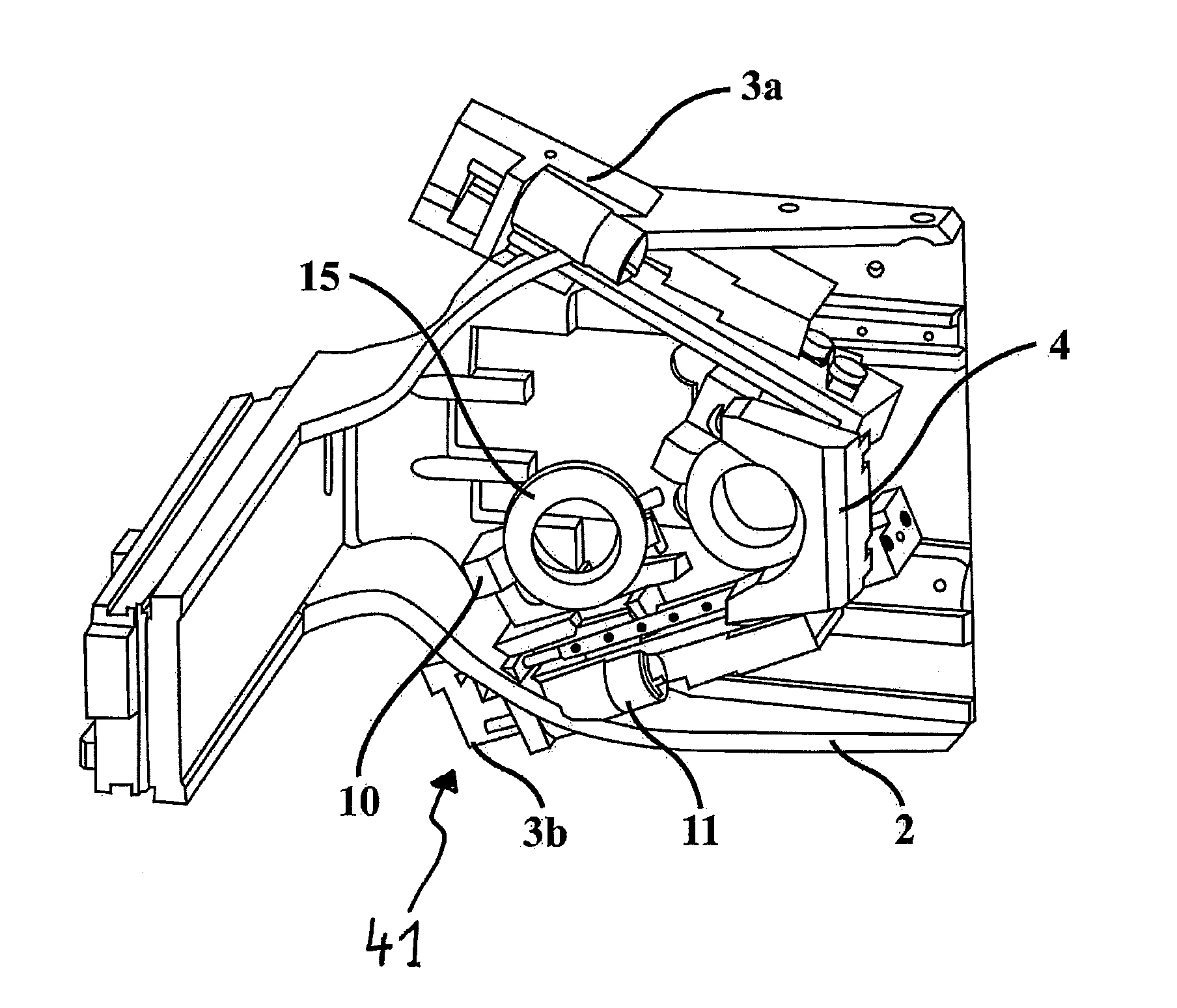
[0023]What is particularly advantageous is a combination of both features mentioned, namely that the slide is movable on the one hand along at least one guide rod which in particular extends in a straight line, and on the other hand that the slide is movable along a guide groove that defines the displacement path from a stand-by position into the operating position. For this, the slide is in particular connected via the at least one guide rod to a guide receptacle of an adjusting unit. Thus, the guide receptacle so to speak holds the at least one guide rod along which the slide moves. On the other hand, the guide groove is in particular formed on a stationary carrier of the adjusting unit. By
coupling the slide and the guide receptacle to the guide groove in the stationary carrier it can now be caused that the slide moves, on the one hand, along the guide rods within the guide receptacle (linear) while, on the other hand, it simultaneously passes through the desired defined displacement path due to the
coupling to the guide groove in the stationary carrier. For this, the guide receptacle of the slide must usefully be movably or pivotably mounted in the stationary carrier. As already described, the displacement path is advantageously comprised mainly of a horizontally extending first area which is bordered by an angled second area by which the objective can be brought into its final operating position (by lowering the same). This solution makes possible a particularly accurate and stable displacement of the objectives.
[0024]Further, it is advantageous if for each slide an own drive is provided. Such a drive can be provided, for example, by a threaded spindle. Alternatively, it is also conceivable to move several slides via one drive, wherein the moving of an objective into the operating position would have to cause the simultaneous moving of the other objectives into their stand-by positions, which in particular in the case of two objectives can be realized relatively easily. The drive can be accomplished either manually or by a motor.
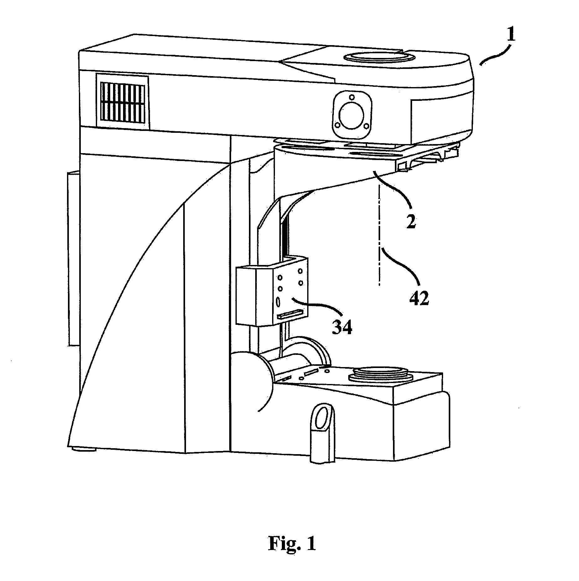
[0028]It is advantageous if the changing device of the objective changer, in particular the mentioned adjusting units for the objectives is or are connected to an intermediate plate on which, for example, a centering
mount for the fixed positioning of an objective holder is arranged. The centering
mount is located at the operating position of the objective and receives the objective holder in a defined spatial position so that an exact alignment of the longitudinal axis of the objective along the optical axis (of the microscope) is guaranteed. The provision of the mentioned intermediate plate makes a
modular structure of the objective changer possible. In the mentioned example of the microscope with objective changer, the mentioned intermediate plate can, for example, be connected to a corresponding counter-receptacle on a support element of the microscope via a dovetail connection. The support element can be adjustable in focusing direction.

