Wavelength division multiplexing and demultiplexing optical structure

A technology of wave division multiplexing and optical structure, applied in the field of high-speed transceiver system wavelength division multiplexing demultiplexing optical structure, can solve the problem that transmission technology is difficult to meet the requirements of transmission capacity and speed, and achieve simple and fast assembly and debugging process , Reduce beam insertion loss, reduce power consumption

Inactive Publication Date: 2014-10-01
SHANGHAI BRANCH FUZHOU GAOYI COMM CO LTD
View PDF3 Cites 18 Cited by
  • Summary
  • Abstract
  • Description
  • Claims
  • Application Information

AI Technical Summary

Problems solved by technology

[0002] With the increasing development of the communication field, traditional transmission technologies have been difficult to meet the requirements of transmission capacity and speed. In typical application fields such as data centers, network connections, search engines, high-performance computing, etc. , carriers and service providers have planned the deployment of a new generation of high-speed network protocols, which requires corresponding high-speed transceiver modules to meet high-density and high-speed data transmission requirements

Method used


Image

  • Wavelength division multiplexing and demultiplexing optical structure
  • Wavelength division multiplexing and demultiplexing optical structure
  • Wavelength division multiplexing and demultiplexing optical structure

Examples


Embodiment Construction

[0021] Below in conjunction with accompanying drawing description and embodiment the present invention will be further described:

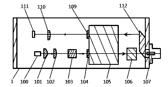
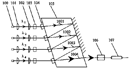
[0022] Such as figure 2 As shown, the optical structure of the transmitting end includes a laser group 100, a first collimating lens group 101, a second correcting lens group 102, a displacement adjustment block group 103, a band-pass filter group 104 at the transmitting end, and a glass block 105. The pass filter group 104 and the lower half of the glass block 105 are combined into a Mux structure, an isolator 106 and a first collimator 107 . exist figure 2 Among them, the laser group 100 includes four lasers, each of which emits laser light of different wavelengths, and a first collimating lens group 101 is arranged at the output end of the laser to collimate the divergent beam emitted by the laser. This lens group adopts An aspheric lens with a small focal length can effectively improve the coupling efficiency; a second correction lens ...


PUM


Abstract

The invention discloses a wavelength division multiplexing and demultiplexing optical structure, which comprises a transmitting end optical structure and a receiving end optical structure, wherein the transmitting end optical structure comprises a wavelength division multiplexing device and a first collimator, and the receiving end optical structure comprises a second collimator and a wavelength division demultiplexing device. The wavelength division multiplexing and demultiplexing optical structure is characterized in that the wavelength division multiplexing device and the wavelength division demultiplexing device are combined to a whole body including a glass block, a transmitting end band-pass filter group and a receiving end band-pass filter group, the transmitting end band-pass filter group is arranged on the lower half part of the glass block, and the wavelength division multiplexing device is formed by the transmitting end band-pass filter group and the lower half part of the glass block; the receiving end band-pass filter group is arranged on the upper half part of the glass block, and the wavelength division demultiplexing device is formed by the receiving end band-pass filter group and the upper half part of the glass block; the receiving end optical structure further comprises a rhombic prism capable of turning a light beam emitted by the second collimator to the wavelength division demultiplexing device. According to the wavelength division multiplexing and demultiplexing optical structure, by adopting micro-optics principle design, the insertion loss of the light beam can be greatly reduced, and the coupling efficiency is improved.

Description

technical field [0001] The invention relates to an optical transceiver module in optical fiber communication technology, in particular to an optical structure for wavelength division multiplexing and demultiplexing in a high-speed transceiver system. Background technique [0002] With the increasing development of the communication field, traditional transmission technologies have been difficult to meet the requirements of transmission capacity and speed. In typical application fields such as data centers, network connections, search engines, high-performance computing, etc. Carriers and service providers have deployed a new generation of high-speed network protocols, which require corresponding high-speed transceiver modules to meet high-density and high-speed data transmission requirements. In the high-speed information transceiver system, it is necessary to replace the traditional optical module with a high-density optical module. Using multi-channel optical transcei...

Claims


Application Information

Patent Timeline
Patent Type & Authority Applications(China)
IPC IPC(8): H04B10/40H04J14/02G02B6/293G02B6/32
Inventor 刘洪彬徐云兵郑睿王向飞李伟启
Owner SHANGHAI BRANCH FUZHOU GAOYI COMM CO LTD
Why Eureka
Try Eureka