Eureka AIR delivers breakthrough ideas for toughest innovation challenges, trusted by R&D personnel around the world.

Method of, and apparatus for, the preliminary grinding and finishing of mineral and non-mineral materials

A non-mineral and material technology, which is applied to the equipment field with the characteristics described in the preamble, can solve the problems of large technical consumption, limitation, material blockage, etc., so as to reduce the technical cost, improve the energy utilization rate, and reduce the mechanical technical loss. Effect

Active Publication Date: 2010-12-15
彼得拉·梅马里·法尔德 +2
View PDF10 Cites 18 Cited by
  • Summary
  • Abstract
  • Description
  • Claims
  • Application Information

AI Technical Summary

Problems solved by technology

[0006] Firstly, the stress of the material layer shows an unacceptable limit when applying a pressure of 600 to 3000kN / m2
[0007] Secondly, the material introduction of the material layers prepared on the circulating slat conveyor requires great technical effort, because the slat conveyor must also be designed for the high-pressure stresses in the loading area, thus in order to control the wear of the traction mechanism and the coating and also To limit noise pollution, speed and flow must be significantly reduced
[0008] Thirdly, the material introduction using a plate conveyor pulled via driven lower rollers results in losses resulting in high machine technology
[0009] Fourth, grinding rollers fed hydraulically and pneumatically to horizontally guided slat conveyors impair material introduction, potentially causing material clogging and material spillage

Method used


Image

  • Method of, and apparatus for, the preliminary grinding and finishing of mineral and non-mineral materials
  • Method of, and apparatus for, the preliminary grinding and finishing of mineral and non-mineral materials
  • Method of, and apparatus for, the preliminary grinding and finishing of mineral and non-mineral materials

Examples


Embodiment Construction

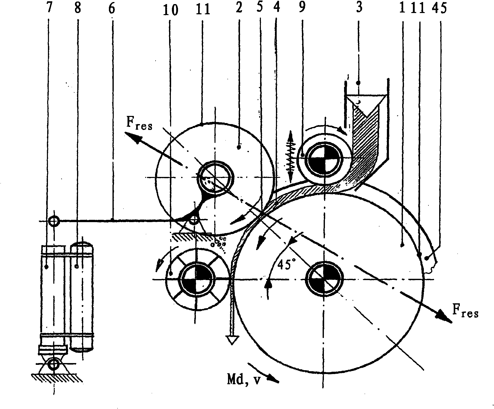
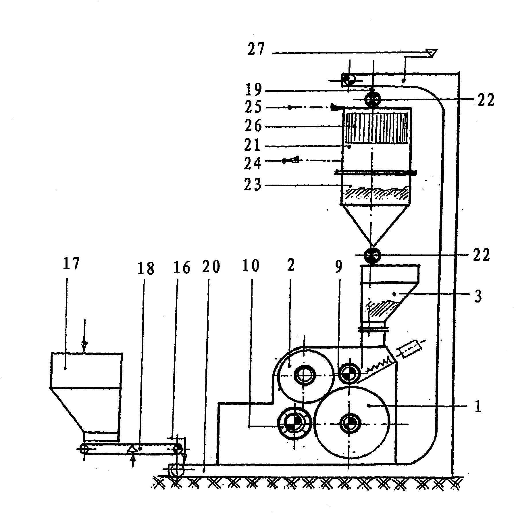
[0054] figure 1 The comminution device of the present invention is shown schematically, which comprises two horizontally supported and staggered rollers 1 and 2 arranged one above the other, an integrated breaker 10 and a system consisting of a feed container 3 and a roller feeder 9. Feeding and discharging device. The lower roller 1 corresponds to the figure 1 are driven in the direction of the arrow shown. Roller 2 is arranged vertically offset from roller 1 above driven roller 1 . The upper roller 2 is fed hydropneumatically towards the roller 1 via a lever system 6 by means of a hydraulic cylinder 7 . The upper roller 2 is dragged by the friction of the load surface of the driven roller 1 covered by the material or substance or can have its own drive. The diameter ratio of the lower roller 2 to the upper roller 2 is preferably 1.0 to 2.0 and particularly preferably 1.0 to 1.5.

[0055] The feed and discharge devices are arranged in the region of the apex of the driven...


PUM


Abstract

In the preliminary grinding and finishing of mineral and non-mineral materials, e.g. limestone, cement clinker, blast-furnace slag, old concrete or ashes, the grinding material, usually comprising new and recirculated stock, is fed as a defined and laterally bounded material layer (4) of predetermined thickness from a material-supply container (3), belonging to the comminuting apparatus, by way of a roller-type or rotary-vane feeder (9), which is arranged at the outlet and can be changed in a stepless manner in respect of its rotational speed, onto the vertex of the laterally rimmed (45), driven, bottom roller (1), accelerated to the roller speed and transported continuously into the gap formed (5) with the top roller (2), arranged in an offset manner above the driven roller (1), is subjected to hydropneumatic loading using specific compressive forces of 2 to 7.5 kN / mm and is then deagglomerated within the comminuting apparatus by a preferably high-speed rotary crusher (10). This results in good utilization of energy and in low mechanical structural, servicing and maintenance outlay. Usage over a wide spectrum for comminuting different materials is made possible, and linear throughput and speed behaviour both in partial-load operation and with high mass throughputs can be realized.

Description

technical field [0001] The invention relates to a method for coarse and fine grinding of mineral and non-mineral materials having the features stated in the preamble of claim 1 and to a method having the features stated in the preamble of claim 8 devices with the features described in the prologue. Background technique [0002] Coarse and fine grinding of hard and brittle materials such as limestone, cement clinker, slag sand, old concrete or ash is usually carried out in ball mills and more recently in vertical-roller mills and also in Realized in a high-pressure-roller mill. [0003] Known by DE 2708053B2 is a so-called material bed roller mill, wherein the comminution of the material is achieved by a single pressure application in the gap between two counter-driven cylindrical rollers, the pressure between the two surfaces exceeds 50Mpa. [0004] A disadvantage is that high-pressure roller mills work with very high pressures, which can only be adjusted under certain co...

Claims


Application Information

Patent Timeline
Patent Type & Authority Applications(China)
IPC IPC(8): B02C4/02B02C4/28B02C4/30B02C4/32B02C4/42
CPCB02C4/42B02C4/30B02C4/02B02C4/32B02C4/286
Inventor F·法伊格A·梅马里·法尔德
Owner 彼得拉·梅马里·法尔德
Why Eureka
Eureka Blog
Learn More