Large mask plate face type compensation device for photoetching equipment

A technology of compensation device and lithography equipment, which is applied in the direction of microlithography exposure equipment, photolithography exposure device, etc., can solve the problems of self-weight deformation of large mask plates, etc., and achieve the goal of improving compensation efficiency, improving imaging quality, and good adsorption effect Effect

Active Publication Date: 2014-09-03
SHANGHAI MICRO ELECTRONICS EQUIP (GRP) CO LTD
View PDF5 Cites 7 Cited by
  • Summary
  • Abstract
  • Description
  • Claims
  • Application Information

AI Technical Summary

Problems solved by technology

[0005] In order to overcome the defects existing in the prior art, the present invention proposes a new large mask surface compensation device, which solves the self-weight deformation of the large mask in the step-and-scan lithography machine without changing the existing hardware structure Compensation problem, so that the self-weight deformation in the field of view of the object side can be effectively controlled during the whole scanning movement of the mask, without the need to adjust the object surface through the objective lens

Method used


Image

  • Large mask plate face type compensation device for photoetching equipment
  • Large mask plate face type compensation device for photoetching equipment
  • Large mask plate face type compensation device for photoetching equipment

Examples


no. 1 example

[0039] Figure 4 It is the first embodiment of the structure of the photolithography system and the compensation device for the large mask template of the present invention.

[0040] Figure 4 The surface compensation device of the illustrated embodiment is located between the lighting unit 1 of the lithography machine and the mask plate 2 , and includes: a glass plate 6 , a support frame for the glass plate, and an exhaust control unit 9 .

[0041] The transparent glass plate 6 is located above the mask plate 2 and arranged parallel to the mask plate 2 , and a number of extraction holes 8 are provided on the glass plate 6 . The glass plate 6 is fixedly arranged relative to the objective lens group 4 and at least covers the current exposure area of ​​the mask plate 2 .

[0042] The exhaust control unit 9 is connected to the exhaust hole 8 through the exhaust pipeline 10, which exhausts the gap between the glass plate 6 and the mask plate 2 through the exhaust hole 8, and for...

no. 2 example

[0051] Figure 5a and Figure 5b It is the second embodiment of the large mask surface compensation device of the present invention.

[0052] Figure 5a and Figure 5b The surface compensation device of the illustrated embodiment is located between the lighting unit of the lithography machine and the mask plate 2, and includes: a glass plate 6, a glass plate support frame 7, and an exhaust control unit.

[0053] The transparent glass plate 6 is located above the mask plate and arranged parallel to the mask plate, and the glass plate 6 is provided with a number of extraction holes. The glass plate 6 is fixedly arranged relative to the objective lens group, and at least covers the current exposure area of ​​the mask plate.

[0054] The exhaust control unit is connected to the exhaust hole through the exhaust pipeline, which exhausts the gap between the glass plate 6 and the mask plate through the exhaust hole, and forms a pressure difference between the upper and lower surfa...


PUM

PropertyMeasurementUnit
transmittivityaaaaaaaaaa

Abstract

The invention discloses a large mask plate face type compensation device for photoetching equipment, which is located between an illumination unit and a mask plate. The large mask plate face type compensation device comprises a glass plate with a plurality of pumping holes, and a pumping control unit, wherein the glass plate is located above the mask plate and is parallel to the mask plate; the glass plate is fixedly arranged relative to an objective lens set and at least covers a current exposure region of the mask plate; the pumping control unit is used for pumping a gap between the glass plate and the mask plate through the pumping holes; a pressure difference is formed between upper and lower surfaces of the mask plate to compensate the self-weight deformation amount of the mask plate. Compared with the prior art, under the condition of not changing an existing hardware framework, a self-weight deformation compensation problem of the large mask plate in a stepping scanning photoetching machine is solved, so that self-weight deformation in an object space view field is effectively controlled in a whole scanning movement process of the mask plate; an object plane does not need to be adjusted through an objective lens.

Description

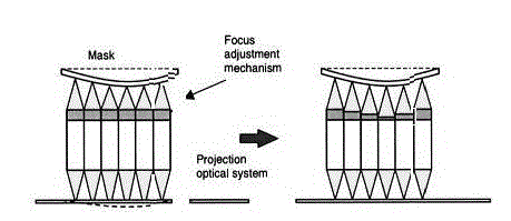
technical field [0001] The invention relates to the field of semiconductor integrated circuit equipment manufacturing, in particular to a large mask template surface compensation device for photolithography equipment. Background technique [0002] With the increase in the size of the thin film field effect transistor TFT substrate, the size of the mask of the TFT lithography machine has also increased accordingly. From the original 6-inch mask to the 5.5th generation of TFT lithography technology, the size of the mask has reached 920mm×800mm , to the 8.5th generation mask size has reached an astonishing 1320mm 1108mm. Such a "huge" mask plate, adsorbed on the mask table, will inevitably be affected by its own weight and deform vertically (up to 40um or more), such as figure 1 shown. For high-generation TFT lithography equipment above the 5.5th generation, multi-lens splicing (Nikon) or ultra-large field of view (Canon) technology is an inevitable trend, and the self-weig...

Claims


Application Information

Patent Timeline
Patent Type & Authority Applications(China)
IPC IPC(8): G03F7/20
Inventor 许琦欣龚辉
Owner SHANGHAI MICRO ELECTRONICS EQUIP (GRP) CO LTD
Why Eureka
Try Eureka