

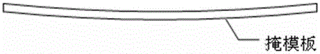
A large mask template surface compensation device for lithography equipment
A technology of compensation device and lithography equipment, which is applied in the direction of microlithography exposure equipment, photolithography exposure device, etc., can solve the problems of self-weight deformation of large mask plates, etc., and achieve the goal of improving compensation efficiency, improving imaging quality, and good adsorption effect Effect
- Summary
- Abstract
- Description
- Claims
- Application Information
AI Technical Summary
Problems solved by technology
Method used
Image

Examples
no. 1 example
[0039] Figure 4 It is the first embodiment of the structure of the photolithography system and the compensation device for the large mask template of the present invention.
[0040] Figure 4 The surface compensation device of the illustrated embodiment is located between the lighting unit 1 of the lithography machine and the mask plate 2 , and includes: a glass plate 6 , a support frame for the glass plate, and an exhaust control unit 9 .
[0041] The transparent glass plate 6 is located above the mask plate 2 and arranged parallel to the mask plate 2 , and a number of extraction holes 8 are provided on the glass plate 6 . The glass plate 6 is fixedly arranged relative to the objective lens group 4 and at least covers the current exposure area of the mask plate 2 .
[0042] The exhaust control unit 9 is connected to the exhaust hole 8 through the exhaust pipeline 10, which exhausts the gap between the glass plate 6 and the mask plate 2 through the exhaust hole 8, and for...
no. 2 example
[0051] Figure 5a with Figure 5b It is the second embodiment of the large mask surface compensation device of the present invention.
[0052] Figure 5a with Figure 5b The surface compensation device of the illustrated embodiment is located between the lighting unit of the lithography machine and the mask plate 2, and includes: a glass plate 6, a glass plate support frame 7, and an exhaust control unit.
[0053] The transparent glass plate 6 is located above the mask plate and arranged parallel to the mask plate, and the glass plate 6 is provided with a number of extraction holes. The glass plate 6 is fixedly arranged relative to the objective lens group, and at least covers the current exposure area of the mask plate.
[0054] The exhaust control unit is connected to the exhaust hole through the exhaust pipeline, which exhausts the gap between the glass plate 6 and the mask plate through the exhaust hole, and forms a pressure difference between the upper and lower sur...
PUM
| Property | Measurement | Unit |
|---|---|---|
| transmittivity | aaaaa | aaaaa |
Abstract
Description
Claims
Application Information