A multi-contact centrifugal switch

A centrifugal switch and multi-contact technology, which is applied in the direction of electric switches, electrical components, circuits, etc., can solve the problems of inflexible control of solenoid valve switches and cumbersome operations, and achieve the effects of long service life, convenient operation, and flexible switching

Active Publication Date: 2016-01-20
彭州市丹景电力机车配件厂
View PDF4 Cites 2 Cited by
  • Summary
  • Abstract
  • Description
  • Claims
  • Application Information

AI Technical Summary

Problems solved by technology

[0004] Aiming at the deficiencies of the above-mentioned prior art, the present invention provides a multi-contact centrifugal switch, which solves the problem that the solenoid valve switch cannot be flexibly controlled and the operation is cumbersome when multiple machines are operating at the same time

Method used


Image

  • A multi-contact centrifugal switch
  • A multi-contact centrifugal switch
  • A multi-contact centrifugal switch

Examples


Embodiment 1

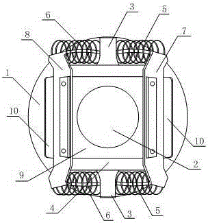
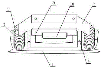
[0029] Such as Figure 1 to Figure 5 As shown, a multi-contact centrifugal switch includes a centrifugal seat and a fixed plate movably connected with the centrifugal seat, the centrifugal seat includes a circular base 1, a first circular through hole is set in the middle of the base, and at both ends of the base Fixing devices are respectively fixedly connected, and the fixing device includes a dead bolt 3 arranged on the outside of the device, and a stand 4 connected to the dead bolt inside the device, the stand is vertically connected to the base, and the centrifugal seat also includes an end The first spring 5 and the second spring 6 fixedly connected with the deadbolt respectively, one end is connected to the other end of the first spring, and the other end is connected to the first pull piece 7 on the other end of the first spring on another fixing device, one end is Connected to the other end of the second spring, the second pull tab 8 connected to the other end of the ...

Embodiment 2

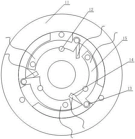
[0036] Such as Figure 1 to Figure 3 As shown, the difference from Embodiment 1 is that the base is fixedly connected to the rotating shaft, and correspondingly, a movable connection seat connected to the lower end of the first pull piece and the second pull piece is set at the same time. The corresponding position of the connection of the second pull piece is provided with a card hole, and the first pull piece and the second pull piece are provided with a blocking member corresponding to the card hole to pass through the card hole, and are used to be movably connected with the movable connection seat. The difference is that when the base is fixed on the rotating shaft, the movable connection seat can move in the space between the base and the blocking groove under the pulling action of the first spring and the second spring through the fixing device.

[0037] Correspondingly, on the base plate, parts such as the first movable contact piece and the connecting reed, the second ...


PUM


Abstract

The invention discloses a multi-contact centrifugal switch. The problems that an electromagnetic switch can not be controlled flexibly and is complex to operate when multiple machines operate at the same time are solved. The centrifugal switch comprises a centrifugal seat and a fixing plate movably connected with the centrifugal seat. The centrifugal seat comprises a base, the two ends of the base are respectively and fixedly connected with a fixing device, and the two ends of each fixing device are connected with a first spring and a second spring respectively. The centrifugal seat further comprises a first pulling piece which is simultaneously connected with the first springs, a second pulling piece which is simultaneously connected with the second springs and a connecting seat which is simultaneously connected with the lower end of the first pulling piece and the lower end of the second pulling piece. The fixing plate is provided with a plurality of first movable contact pieces which are movably connected with the centrifugal seat and connecting spring pieces which are controlled to be opened and closed by the first movable contact pieces. According to the multi-contact centrifugal switch, the switch is controlled by centrifugal force generated by a rotating shaft when the machines operate and is not controlled manually, operation of multiple machines can be controlled, and the multi-contact centrifugal switch is suitable for the condition that the multiple machines operate simultaneously and is convenient to operate.

Description

technical field [0001] The invention belongs to the field of mechanical manufacturing, and in particular relates to a multi-contact centrifugal switch. Background technique [0002] A switch is an electronic component that can open a circuit, interrupt the current flow, or allow it to flow to other circuits. Switches are classified according to their uses: power switches, limit switches, control switches, transfer switches, isolating switches, wall switches, intelligent fire switches, etc.; according to their structure, they are divided into: micro switches, toggle switches, button switches, key switches , as well as fashionable membrane switches and point switches; classified according to the number of switches: single-control switch, double-control switch, multi-control switch, dimmer switch, doorbell switch, sensor switch, touch switch, remote control switch, etc.; the most common A switch is an electromechanical device operated by a person, in which there is one or seve...

Claims


Application Information

Patent Timeline
Patent Type & Authority Patents(China)
IPC IPC(8): H01H35/10
Inventor 周贤勇
Owner 彭州市丹景电力机车配件厂
Why Eureka
Try Eureka