
Binding device for overhead lead and stay wire

A technology for overhead wires and binding devices, which is applied in the direction of adjusting/maintaining mechanical tension, which can solve the problems of inconvenient operation, reducing the toughness of aluminum wires, and time-consuming, so as to shorten the working time, improve the safety factor, and bind tightly and reliably. Effect

Inactive Publication Date: 2014-09-03
STATE GRID CORP OF CHINA +2
View PDF6 Cites 3 Cited by
  • Summary
  • Abstract
  • Description
  • Claims
  • Application Information

AI Technical Summary

Problems solved by technology

[0005] First, in actual operation, the use of pliers and other tools will inevitably damage the binding wire itself
For example: for aluminum binding wires, the pliers will cause physical damage to the aluminum wires, reducing the toughness of the aluminum wires and causing safety hazards; for galvanized iron wires, during operation, the pliers will remove the galvanized iron wire The layer is scraped off, destroying the structure of the galvanized iron wire, making it easy to be corroded and rusted, causing serious problems in terms of durability and reliability
[0006] Second, when adopting the traditional craft, the wire binding should be coiled into a circle with a diameter of about 10 cm, and the coiled iron wire should not be too long (usually 2 meters per coil)
Otherwise, it is not only time-consuming and labor-intensive, but also inconvenient to operate

Method used


Image

  • Binding device for overhead lead and stay wire
  • Binding device for overhead lead and stay wire

Examples


Embodiment Construction

[0031] Below in conjunction with accompanying drawing and embodiment the present invention is described in further detail:

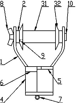
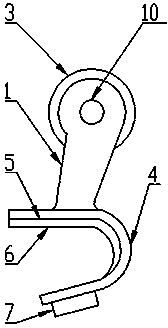
[0032] Binding devices for overhead conductors and guy wires, such as figure 1 and figure 2 As shown, it includes a device body, a reel 3, a binding arc 4, and a jack 7.

[0033] The illustrated reel 3 is arranged on the upper end of the device body, and passes through a central shaft 10 between two opposite support arms 1 . The support arm frame 1 is made of plate metal, and the metal plates of the two support arm frames 1 are parallel to each other. The upper part of the support arm frame 1 corresponding to the installation of the winding wheel 3 is set in a disc shape, and the center of the disc shape is provided with a central hole. And the middle part of the disc shape protrudes slightly outwards, and the outer edge of the disc shape slightly closes inward.

[0034] The winding wheel 3 includes a winding shaft 31 and two retaining wheels 32 . T...


PUM

PropertyMeasurementUnit
Inner diameteraaaaaaaaaa
Outer diameteraaaaaaaaaa
End diameteraaaaaaaaaa

Abstract

The invention discloses a binding device for an overhead lead and a stay wire. The binding device comprises a device body, wherein one end of the device body is provided with two parallel supporting arm racks, a reel wheel is mounted between the two supporting arm racks through a center shaft, a damping fin is mounted between two ends of the reel wheel and the supporting arm racks, one end of the center shaft stretches out of the supporting arm racks and is equipped with an adjusting valve used for adjusting tightness of the supporting arm racks and the reel wheel, the other end of the device body is provided with a binding arc used for accommodating the overhead lead or the stray wire, an opening direction of the binding arc is perpendicular to an axial direction of the center shaft, one side of the binding arc is connected with the supporting arm racks, a notch end face of the one side of the binding arc is provided with a first clamping block and a second clamping block with intervals along an axial direction, the first clamping block and the second clamping block are in smooth connection with an inner side face of the binding arc, a distance from the first clamping block to the inner side face of the binding arc face at an opposite side is greater than a distance from the second clamping block to the inner side face of the binding arc face at the opposite side. The binding device has advantages of reasonable design, simple structure, time-saving labor-saving performance, convenient and reliable performance and convenient operation.

Description

technical field [0001] The invention relates to a tool for installing cables and wires, in particular to a binding device for binding overhead conductors or pull wires. Background technique [0002] The power supply environment in mountainous areas is complex and involves a wide range of work. The users under its jurisdiction cover almost all types of electricity consumption such as large-scale industry, general industry, breeding, agricultural production, and general residential life. The task of power supply is heavy, and there are many construction tasks. The electricity purchased and sold was nearly 100 million kWh at its peak. [0003] In the power supply work, line erection is an indispensable part, and whether the line is firm or not depends to a large extent on the binding process of overhead wires and poles. For example: in electric power overhead lines, when encountering overhead wires fixed by dish insulators, it is necessary to bind the overhead wires with alumi...

Claims


Application Information

Patent Timeline
IPC IPC(8): H02G7/02
Inventor 刘占雄冀建波康海信赵宝军张宇
Owner STATE GRID CORP OF CHINA
Learn More