
Method and device of self-adaptive video diagnosis

A diagnostic method and self-adaptive technology, applied in the direction of television, closed-circuit television system, electrical components, etc., can solve the problems of alarm influence, large misdiagnosis, insufficient flexibility, etc., and achieve the effect of reducing false detection.

Active Publication Date: 2014-09-03
ZHEJIANG UNIVIEW TECH CO LTD
View PDF7 Cites 8 Cited by
  • Summary
  • Abstract
  • Description
  • Claims
  • Application Information

AI Technical Summary

Problems solved by technology

[0004] The flexibility of this solution is not enough. For example, if the daytime diagnosis solution encounters a cloudy or rainy day, it will have a serious impact on the video diagnosis alarm.
In the environment of some large-scale video surveillance networks (tens of thousands of front-end devices), the time span is relatively large, and the diagnosis results during the day and night are quite different, resulting in a relatively high probability of misdiagnosis in actual use.

Method used


Image

  • Method and device of self-adaptive video diagnosis
  • Method and device of self-adaptive video diagnosis
  • Method and device of self-adaptive video diagnosis

Examples


Embodiment 1

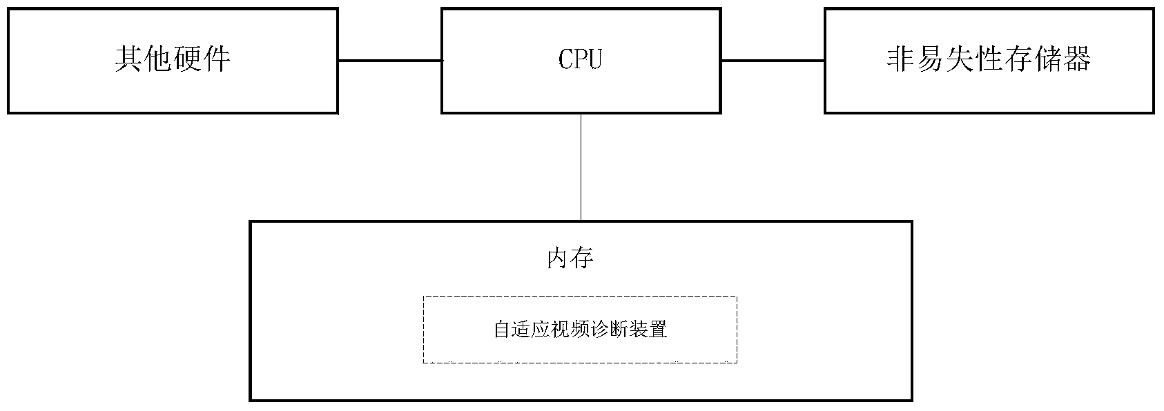
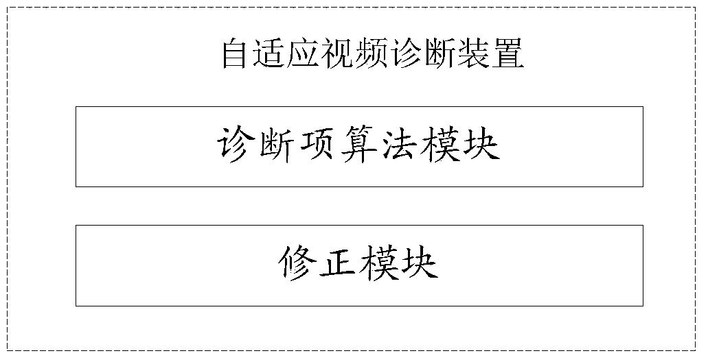
[0026] The self-adaptive video diagnosis device of Embodiment 1 includes: a diagnostic item algorithm module and a correction module, please refer to figure 2 . The use and operation of the device includes the following steps, please refer to image 3 :

[0027] Step 11, the diagnosis item algorithm module calculates the diagnosis item result A of the video image currently output by the front-end camera according to the diagnosis item algorithm.

[0028] The video diagnosis server can obtain video image data from the front-end camera according to the diagnosis plan, and then use the diagnosis item algorithm to diagnose each video diagnosis item according to the obtained video image data. Each diagnostic item may include image brightness, sharpness, color, etc. In the prior art, there may be various diagnostic item algorithms for different diagnostic items, and the present invention has no limitation on which algorithm is used to calculate the diagnostic items. The followi...

Embodiment 2

[0036] In most cases, before obtaining the diagnostic item result A of the current video image, the video diagnostic server has already diagnosed the diagnostic item results of several video images, and these results are used for statistical calculation to obtain the diagnostic item B of the diagnostic item. Embodiment 1 belongs to this case. But when the system is just started, there is no above result B. For example, the video diagnosis server starts to perform 24-hour video diagnosis at zero o'clock on Monday, Wednesday and Friday every week, and there are not n video images in the first few minutes of performing video diagnosis every Monday, Wednesday and Friday. The statistical result B of the corresponding diagnosis item; only after running for a period of time, can the calculation of the result B be performed according to the corresponding diagnosis items of the currently obtained n video images. In the initial period of time, how to correct the result A of the diagnos...


PUM


Abstract

The invention provides a method of self-adaptive video diagnosis, which is applied to a video diagnosis server. The method comprises the following steps of: step 1, figuring out a result A of a diagnosis item of a currently-output video image of a front-end camera according to a diagnosis item algorithm; step 2, correcting the result A of the diagnosis time through a correction value, which is obtained by figuring up a standard result S of the diagnosis item and a result B of the diagnosis item of n previous video images obtained by current statistics, and outputting the corrected result of the diagnosis item. According to a scheme of the invention, a feedback mechanism is introduced in a video diagnosis system, so that the video diagnosis system is capable of correcting an output result as an input factor in a real-time manner, self-adaption is carried out on the environment of video diagnosis, and the false detection, which is caused by the change of environment, of the video diagnosis is reduced.

Description

technical field [0001] The present invention relates to the technical field of video monitoring, in particular to an adaptive video diagnosis method and device Background technique [0002] With the continuous expansion of the monitoring network scale, there are more and more video acquisition devices in the video monitoring network. How to effectively diagnose the abnormality of the front-end equipment through the video diagnosis system in a timely and accurate manner is becoming more and more important. At present, many manufacturers have invested in the field of video diagnosis, but the video diagnosis systems of each manufacturer have the problem of poor environmental adaptability. When the video surveillance network to be diagnosed is relatively large, serious no-alarms may occur. For example, a video surveillance network needs to diagnose continuously for 12 hours. Due to the large time span, the surrounding environment will change greatly. In this way, the diagnostic...

Claims


Application Information

Patent Timeline
Patent Type & Authority Applications(China)
IPC IPC(8): H04N7/18H04N17/00
Inventor 王江柱
Owner ZHEJIANG UNIVIEW TECH CO LTD
Learn More