
Shank tool

A chisel and chisel head technology, applied in roads, manufacturing tools, road repairs, etc., to achieve the effect of small friction and wear, reliable surface pressure

Inactive Publication Date: 2014-09-03
BETEK +1
View PDF11 Cites 9 Cited by
  • Summary
  • Abstract
  • Description
  • Claims
  • Application Information

AI Technical Summary

Problems solved by technology

Additional parts costs are required for clamping sleeves and wear plates

Method used


Image

  • Shank tool
  • Shank tool
  • Shank tool

Examples


Embodiment Construction

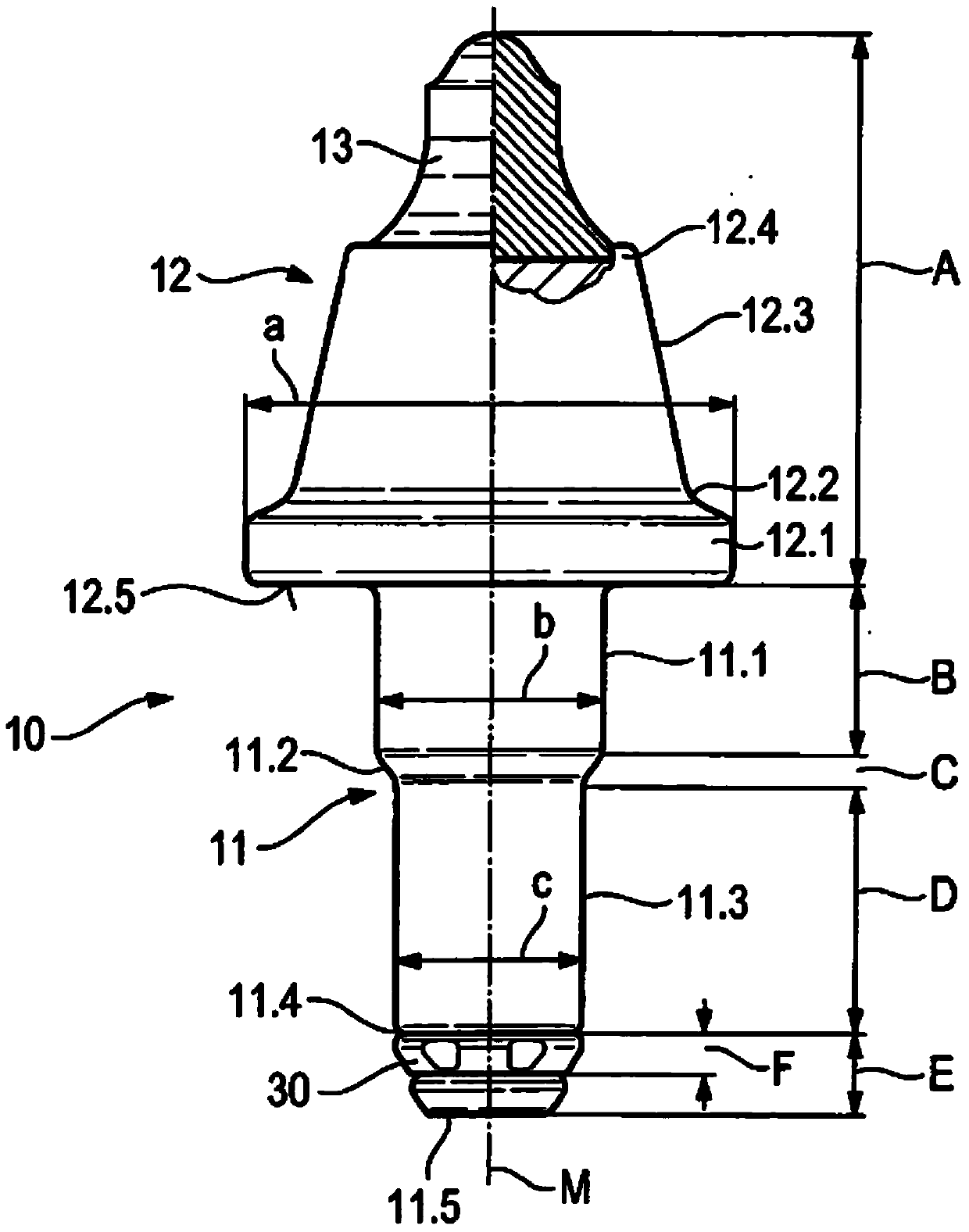
[0039] figure 1 Shown is a shank chisel 10 with a chisel shank 11 and a chisel head 12 formed on it. The chisel shank 11 is designed as a multi-stage shank and has a first cylindrical section 11.1 which transitions via a frustoconical transition section 11.2 into a second cylindrical section 11.3 in the region of the second cylindrical section 11.3 A safety receiver 11.4 in the form of an annular groove is provided in the middle. The safety receptacle 11.4 is delimited at the end by a collar 11.5. The first cylindrical section 11.1 is directly connected to the support surface 12.5 of the chisel head 12 via a circular transition or alternatively via a frusto-conical transition section. A stress-optimized contour shape has proven to be advantageous when using a frustoconical transition section with a cone angle of 45° and an extension of less than 4 mm in the direction of the central longitudinal axis M of the chisel shank 11 . The support surface 12.5 is annular here and is...


PUM

PropertyMeasurementUnit
Diameteraaaaaaaaaa
Outer diameteraaaaaaaaaa

Abstract

The invention relates to a shank tool for a road milling machine or the like, having a tool head (12) and a tool shank (11), wherein the tool shank (11) has a first cylindrical section (11.1) which indirectly or directly adjoins the tool head (12), and wherein the tool shank (11) has a second cylindrical section (11.3) which is remote from the tool head (12) and indirectly or directly adjoins the first cylindrical section (11.1), and wherein the diameter (c) of the second cylindrical section (11.3) differs from the diameter (b) of the first cylindrical section (11.1). With such a shank tool, improved use properties arise in that the first cylindrical section (11.1) has a diameter (b) in the range between 18 mm and 30 mm and an extent (B) in the direction of the centre longitudinal axis of the tool shank of less than 30 mm.

Description

technical field [0001] The invention relates to a shank chisel for a road milling machine or the like, having a chisel head and a chisel shank, wherein the chisel shank has a first cylindrical section which is connected directly or indirectly to the chisel On the bit, and the chisel shank has a second cylindrical section, which deviates from the chisel head and is directly or indirectly connected to the first cylindrical section, wherein the diameter of the second cylindrical section is the same as that of the first cylinder The diameters of the shaped segments are different. Background technique [0002] Such a shank chisel is known from DE 33 07 895 A1. In this case, the chisel shank is designed as a stepped shank, in which two cylindrical sections of different diameters are provided. The first cylindrical section is directly connected to the bit and has a larger diameter than the second cylindrical section. The second cylindrical section forms the longitudinal end of t...

Claims


Application Information

Patent Timeline
IPC IPC(8): E21C35/18E21C35/197E01C23/088
CPCE21C35/18B28D1/186E21C35/197
Inventor M·罗思T·奥盖尔T·莱纳特
Owner BETEK
Learn More