Check patentability & draft patents in minutes with Patsnap Eureka AI!

Driving of electrowetting display device

A technology of electrowetting display and display device, applied in static indicators, cathode ray tube indicators, instruments, etc., can solve problems such as unsatisfactory image display

Active Publication Date: 2014-09-03
LIQUAVISTA BV
View PDF10 Cites 3 Cited by
  • Summary
  • Abstract
  • Description
  • Claims
  • Application Information

AI Technical Summary

Problems solved by technology

Known display devices operated by known

Method used


Image

  • Driving of electrowetting display device
  • Driving of electrowetting display device
  • Driving of electrowetting display device

Examples


Example Embodiment

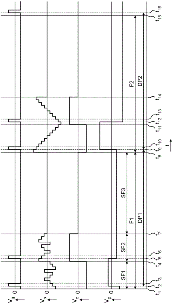
[0021] According to the first embodiment, there is provided a method of driving an electrowetting display device including at least one pixel, the method including the following steps for maintaining the display state of the pixel during a display period:

[0022] Applying a first pixel voltage to the pixel during the first part of the display period, the first pixel voltage corresponding to the display state; and

[0023] A second pixel voltage is applied to the pixels during the second part of the display period, the second pixel voltage corresponds to the display state and the first pixel voltage and the second pixel voltage have different polarities.

[0024] The unsatisfactory aspect of the image displayed by the known display device is that the display state is not maintained in a longer display period (ie, at a low frame rate), regardless of the fact that the pixel voltage remains at the same level during the display period. The method according to the embodiment inverts the p...


PUM


Abstract

A method of driving an electrowetting display device including at least one pixel, the method comprising: applying a first pixel voltage to the pixel during a first portion of the display period; and applying a second pixel voltage to the pixel during a second portion of the display period, the first and second pixel voltages corresponding to a display state of the pixel, and the first pixel voltage and the second pixel voltage having different polarities.

Description

technical field [0001] The present invention relates to a method of driving an electrowetting display device, a display driving system suitable for using the method, and a display device comprising the display driving system and the electrowetting display device. Background technique [0002] Known electrowetting display devices have a plurality of picture elements or pixels and methods of driving the pixels. A pixel includes a first non-conductive fluid and a second conductive fluid. The position of the first fluid in the pixel is controlled by the applied voltage and causes a display effect that provides the displayed state of the pixel. When driving a pixel, the polarity of the voltage applied to the pixel changes between each successive frame or scan period. A known method combined with applying an alternating voltage to the second fluid and a constant voltage to one of the plates of the energy storage capacitor of the pixel is illustrated to account for the dependence...

Claims


Application Information

Patent Timeline
IPC IPC(8): G09G3/34
CPCG09G2320/0204G09G2320/043G09G2320/0219G09G3/348G09G2310/0256G09G5/18
Inventor 约瑟夫·伊丽莎白·奥贝特亨利克斯·彼得罗妮拉·玛丽亚·德克斯博克·约翰内斯·芬斯特拉安东尼·约翰·斯莱克
Owner LIQUAVISTA BV
Features
  • R&D
  • Intellectual Property
  • Life Sciences
  • Materials
  • Tech Scout
  • Unparalleled Data Quality
  • Higher Quality Content
  • 60% Fewer Hallucinations
Learn More