Impeller manufacturing process and lateral blade cut punching-bending forming die

A manufacturing process and forming die technology, applied in the field of punching and bending forming die for side blade incision, can solve the problems of inability to ensure smooth operation of the fan, poor rigidity and strength, etc., and achieve reliable manufacturing process, good rigidity and strength, and simple die structure. Effect

Inactive Publication Date: 2014-09-10
SUZHOU INST OF INDAL TECH
View PDF4 Cites 0 Cited by
  • Summary
  • Abstract
  • Description
  • Claims
  • Application Information

AI Technical Summary

Problems solved by technology

[0004] The purpose of the present invention is to provide a manufacturing process of the impeller to solve the technical problem that the rigidity and strength of the impeller of the metal assembly or injection molded part in the prior art are poor, and the smooth operation of the fan cannot be guaranteed after a period of operation

Method used


Image

  • Impeller manufacturing process and lateral blade cut punching-bending forming die
  • Impeller manufacturing process and lateral blade cut punching-bending forming die
  • Impeller manufacturing process and lateral blade cut punching-bending forming die

Examples


Embodiment Construction

[0038] The present invention will be described in detail below in conjunction with the accompanying drawings and embodiments.

[0039] The manufacturing process of the impeller of the present invention comprises the following steps:

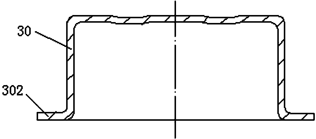
[0040] a. Blanking and deep drawing: a metal sheet is drawn and blanked to form a drawn part with a flange, such as figure 1 As shown, wherein, the drawing part 30 includes a cup-shaped body, and the bottom of the cup-shaped body has a flange 302 . This step can be completed by the blanking and deep drawing die in the prior art, and the metal sheet can be aluminum sheet L1060.

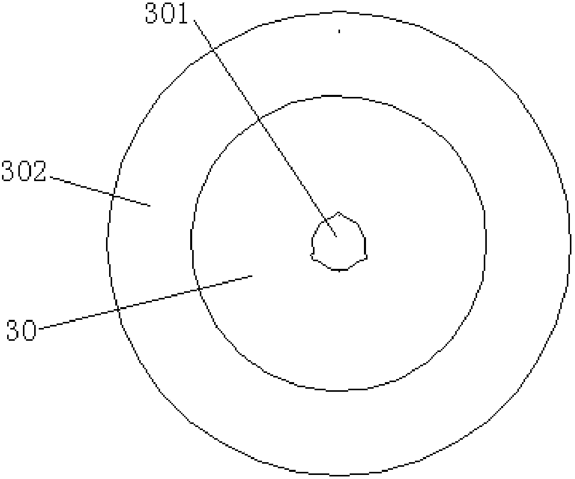
[0041] b. top surface punching: a shaft hole 301 is punched out in the center of the top surface of the drawn part 30, such as figure 2 Shown; This step can be finished by punching die in the prior art.

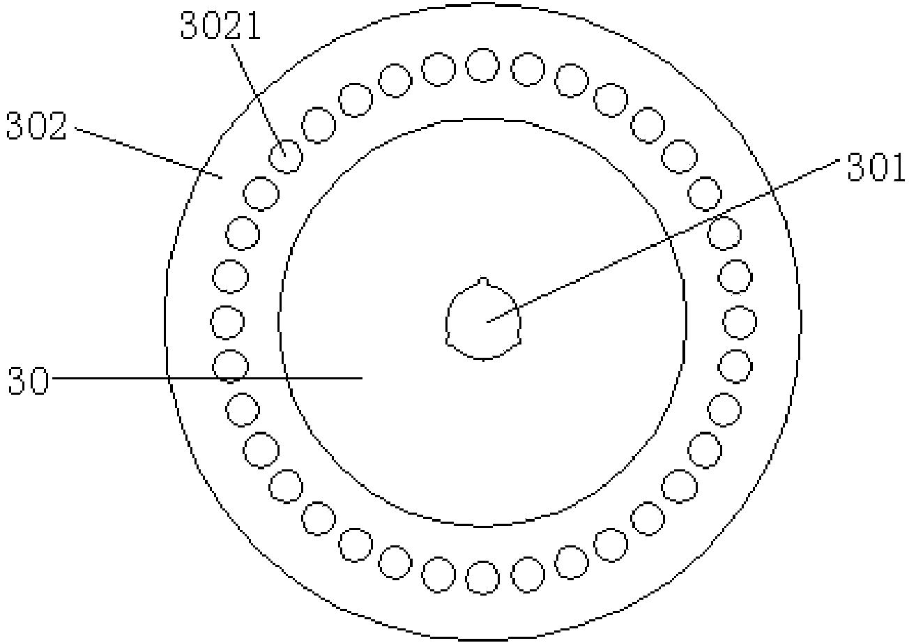
[0042] c. Flange punching: 36 positioning process holes 3021 are uniformly punched out along the circumferential direction of the flange 302 of the drawing part 30, ...


PUM


Abstract

The invention provides an impeller manufacturing process and a lateral blade cut punching-bending forming die. The manufacturing process includes the steps of a, blanking and drawing, to be more specific, blanking and drawing a metal plate to form a drawn part with a flange, wherein the drawn part comprises a cup-shaped body, and the flange is disposed at the bottom of the cup-shaped body; b, punching top surface, to be more specific, punching a shaft hole in the center of the top surface of the drawn part; c, punching the flange, to be more specific, evenly punching a plurality of positioning process holes along the periphery of the flange of the drawn part; d, performing lateral blade cut punching-bending forming, to be more specific, using the lateral blade cut punching-bending forming die to punch all blade grooves; e, cutting the flange of the drawn part. Compared with the prior art, the manufacturing process has the advantages that the impeller manufactured by the process is of an integral metal structure and good in rigidity and strength, equal division precision and consistence of the blades are high, balancing indexes can be satisfied, and long-term stable operation of a fan can be guaranteed.

Description

technical field [0001] The invention relates to the technical field of a centrifugal fan, in particular to a manufacturing process of an impeller and a specially designed side blade notch punching and bending forming die for implementing the manufacturing process. Background technique [0002] A centrifugal fan generally includes components such as an impeller, a motor, and a casing. The main shaft of the motor is connected to the impeller, and the motor drives the impeller to rotate. The centrifugal fan is based on the principle of converting kinetic energy into potential energy. It uses a high-speed rotating impeller to accelerate the gas, then decelerates, changes the flow direction, and converts kinetic energy into potential energy (pressure). In the centrifugal fan, the gas enters the impeller from the axial direction, the air flow changes to the radial direction through the impeller, and flows out from the side of the impeller. The current impeller is generally a meta...

Claims


Application Information

Patent Timeline
Patent Type & Authority Applications(China)
IPC IPC(8): B21D35/00B21D37/10
Inventor 肖洪波徐立华殷铭成立
Owner SUZHOU INST OF INDAL TECH
Why Eureka
Try Eureka