
Small-displacement high-precision pitch-change mechanism

A pitch-variable mechanism and high-precision technology, which is applied in the direction of assembly machines, metal processing, metal processing equipment, etc., can solve the problems of oil cylinder or cylinder leakage that cannot be guaranteed to be in a precise position, pressure that cannot be detected, and easily damaged workpieces. Achieve the effects of simple structure, low cost, and guaranteed press-fitting quality

Inactive Publication Date: 2014-09-10
ANHUI GSTONE AUTOMATION EQUIP
View PDF6 Cites 7 Cited by
  • Summary
  • Abstract
  • Description
  • Claims
  • Application Information

AI Technical Summary

Problems solved by technology

[0003] When press-fitting the parts on the intermediate shaft, if the center deviation is relatively large, multiple compact oil cylinders are usually used to correspond to each type, and the cost is high; for the case of small center deviation, a transition is usually manually placed on the workpiece The pressure head and the upper cylinder are pressed on the end surface of the transition pressure head. This situation can basically ensure that the pressure is in place, but because the pressure is not concentric, the pressure cannot be detected, and the workpiece is easily damaged.
In order to reduce the cost and improve the assembly quality, we tried to fix the oil cylinder on a horizontal sliding mechanism, and use the oil cylinder or air cylinder to drive to realize the switching position, but when working in one position for a long time, the leakage of the oil cylinder or air cylinder cannot be guaranteed to be in an accurate position all the time. position, we can only add a positioning pin driven by a cylinder in the vertical direction, and then a new problem arises. For positions with relatively small distances, most of the positioning pins will overlap, and this method cannot be used for positioning

Method used


Image

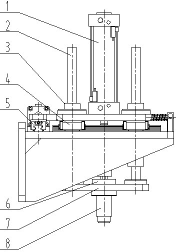
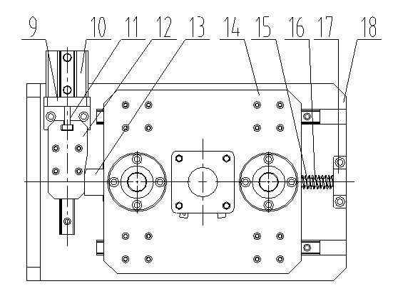
  • Small-displacement high-precision pitch-change mechanism
  • Small-displacement high-precision pitch-change mechanism

Examples


Embodiment Construction

[0019] In order to make it easy to understand the technical means, creative features, work flow, and use methods of the present invention to achieve the purpose and effect, the technical solutions in the embodiments of the present invention will be clearly and completely described below in conjunction with the embodiments of the present invention. Obviously, the The described embodiments are only some, not all, embodiments of the present invention. Based on the embodiments of the present invention, all other embodiments obtained by persons of ordinary skill in the art without making creative efforts belong to the protection scope of the present invention.

[0020] Such as figure 1 , figure 2 As shown, a small-displacement high-precision distance variable mechanism includes: an oil cylinder 1, an air cylinder 10, and a fixed seat 18. A pair of horizontal-axis slide rails 4 is arranged on the fixed seat 18; the sliding plate 14 is fixed on the horizontal-axis slide rail 4 The...


PUM


Abstract

The invention provides a small-displacement high-precision pitch-change mechanism which comprises an oil cylinder, guide rods, an air cylinder, a stop block and a fixing seat, wherein a pair of cross shaft slide rails is arranged on the fixing seat; a slide plate is mounted on the cross shaft slide rail; the oil cylinder and linear bearings are fixed on the slide plate; the guide rods is fixed with a pressure plate together; the inner end of a floating joint is connected with an oil cylinder rod of the oil cylinder; the air cylinder is fixed with the fixing seat together via an air cylinder seat; and the air cylinder drives a step locating block to move back and forth via an air cylinder joint.The mechanism can achieve automatic and accurate location of a pressure head, achieve that middle shafts of every gearbox can be subjected press mounting coaxially, and ensure press mounting quality, the position of the mechanism cannot be changed due to leakage of compressed air or a hydraulic station, and the mechanism is stable, reliable, low in cost, simple in structure and convenient to maintain.

Description

technical field [0001] The invention relates to the technical field of pitch-variable mechanisms, in particular to a small-displacement, high-precision pitch-variable mechanism. Background technique [0002] The gearbox is the transmission system of the car, which is responsible for connecting the car engine and the axle, and controlling the speed and torque transmitted to the axle. It is an extremely important part of the car. On the flexible assembly line of automotive manual transmissions, the output shaft and the intermediate shaft are usually positioned together on a pallet or box for installation, and the center of the output shaft is used as the reference, and the center of the intermediate shaft usually does not coincide due to different models. [0003] When press-fitting the parts on the intermediate shaft, if the center deviation is relatively large, multiple compact oil cylinders are usually used to correspond to each type, and the cost is high; for the case of s...

Claims


Application Information

Patent Timeline
Patent Type & Authority Applications(China)
IPC IPC(8): B23P21/00
CPCB23P19/02
Inventor 何凯张彦海俞锋
Owner ANHUI GSTONE AUTOMATION EQUIP
Learn More