High-power cable output machine

A technology for power cables and output machines, which is applied in the directions of transportation and packaging, thin material handling, and filamentary material transportation, can solve the problems of slow transportation and achieve the effect of ensuring safe transmission.

Active Publication Date: 2014-09-10
STATE GRID SICHUAN ELECTRIC POWER
View PDF8 Cites 2 Cited by
  • Summary
  • Abstract
  • Description
  • Claims
  • Application Information

AI Technical Summary

Problems solved by technology

[0003] The purpose of the present invention is to overcome the shortcomings and deficiencies of the above-mentioned prior art, provide a high-power cable output machine, and solve the defect of slow delivery speed of the existing cable conveyor

Method used


Image

  • High-power cable output machine
  • High-power cable output machine
  • High-power cable output machine

Examples


Embodiment Construction

[0016] Below in conjunction with embodiment the present invention is described in further detail, but structure of the present invention is not limited to following embodiment:

[0017] 【Example】

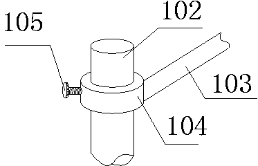
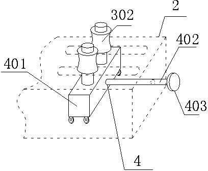
[0018] Such as Figure 1-6 As shown, the high-power cable output machine includes a support device 1 and a conveying device 2. The support device 1 includes two support rollers 101, and the support roller 101 includes two vertically arranged legs 102, and is arranged on The roller 103 between the two legs 102, the conveying device 2 is located between the two support rollers 101, which includes a cabinet body 201, and two roller drives 3, and the roller drives 3 are all arranged in the cabinet The upper end surface of the body 201 includes a moving roller 301 and a static roller 302. The axles of the moving roller 301 and the static roller 302 are all vertical, and all the static rollers 302 are arranged in a straight line. Perpendicular to the straight line passing through all th...


PUM


Abstract

The invention discloses a high-power cable output machine which comprises a supporting device (1) and a conveying device (2). The supporting device (1) comprises two supporting drums (101), the conveying device (2) is positioned between the supporting drums (101) and comprises a cabinet body (201) and at least two roller drivers (3), each roller driver (3) comprises a movable roller (301) and a static roller (302), each of the movable rollers (301) and the static rollers (302) is driven by a motor to rotate, and an annular pressure sensor (5) is arranged between a body (304) of each static roller (302) and a wheel shaft of the corresponding static roller (302). The high-power cable output machine has the advantages that multiple groups of rollers are arranged, and each roller is driven by the corresponding motor solely, so that power output is guaranteed; by arranging the sensors to test clamping force, applied on a cable, of the static rollers and the movable rollers, safety in conveying of the cable is guaranteed due to the clamping force which is moderate.

Description

technical field [0001] The invention relates to a cable conveying device, in particular to a high-power cable output machine. Background technique [0002] In existing cities, wires and cables traveling in the air affect the city appearance too much. Nowadays, most cables pass through the ground. When laying cables underground, they are usually transported by cable conveying devices. Usually, the cables are clamped by rollers, and then After the rollers roll, the cable is conveyed, but the existing conveying device uses two rollers to clamp the cable, and one is the main roller, and the other is the driven roller. When conveying, the transmission speed of the cable is very slow, which affects the work progress. Contents of the invention [0003] The object of the present invention is to overcome the shortcomings and deficiencies of the above-mentioned prior art, provide a high-power cable output machine, and solve the defect of slow conveying speed of the existing cable c...

Claims


Application Information

Patent Timeline
Patent Type & Authority Applications(China)
IPC IPC(8): B65H51/08B65H51/32
Inventor 李季张新梁益勤
Owner STATE GRID SICHUAN ELECTRIC POWER
Why Eureka
Try Eureka