Combined wind shield for high-speed railway bridge

A wind barrier and combined technology, applied in buildings, protective equipment, etc., can solve problems such as bridge damage and fatigue damage, achieve the effect of reducing wind load force, reducing additional costs, and ensuring normal design and operation

Active Publication Date: 2014-09-10
CENT SOUTH UNIV +1
View PDF3 Cites 11 Cited by
  • Summary
  • Abstract
  • Description
  • Claims
  • Application Information

AI Technical Summary

Problems solved by technology

In order to solve the fatigue damage of the existing fixed wind barrier under the action of continuous cross wind; the wind barrier transmits the high wind load received to the bridge, thus causing the technical problem of bridge damage

Method used


Image

  • Combined wind shield for high-speed railway bridge
  • Combined wind shield for high-speed railway bridge
  • Combined wind shield for high-speed railway bridge

Examples


Embodiment Construction

[0034] The following is a further description of the technical content of the patent of the present invention, but it is not a limitation to the essential content of the patent of the present invention.

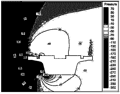
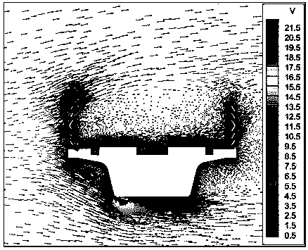
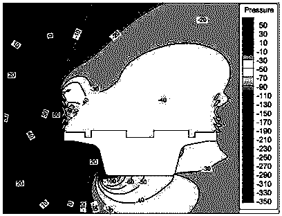
[0035] figure 1 It is a structural schematic diagram of a combined wind barrier for a railway bridge according to an embodiment of the present invention; figure 2 It is a structural schematic diagram of a combined wind barrier for a railway bridge in an initial state according to an embodiment of the present invention; image 3 It is a structural schematic diagram of a combined wind barrier for railway bridges with windshield blades rotated 30° in an embodiment of the present invention; Figure 4 It is a structural schematic diagram of a combined wind barrier for railway bridges when the windshield blades of the embodiment of the present invention rotate to the same direction as the wind direction; Figure 5 It is a structural schematic diagram of a combined wind barrier f...


PUM


Abstract

The invention discloses a combined wind shield for a high-speed railway bridge. The wind shield comprises at least two stand columns, wherein a gap is reserved between every two stand columns, bottoms of the stand columns are fixed on the ground or on a base, and a first wind blocking assembly and a second wind blocking assembly which are used for blocking crosswind are arranged between every two adjacent stand columns; each first wind blocking assembly comprises two first wind blocking blades for blocking the crosswind and a first connecting shaft for connecting the two first wind blocking blades, plate edges of every two first wind blocking blades are connected through a connecting shaft, and at least one first wind blocking blade can rotate with each first connecting shaft serving as a rotating shaft; each second wind blocking assembly comprises a second wind blocking blade for blocking the crosswind and a second rotating shaft, and the plate edge of each second wind blocking blade is connected with each second rotating shaft and rotates along with each second rotating shaft. The effect transmitted by the combined wind shield to the bridge at the lower part is reduced, the normal design and operation of the bridge are guaranteed, and the extra cost caused by resistance to the crosswind is reduced.

Description

technical field [0001] The invention relates to the technical field of railway bridge devices, in particular to a combined wind barrier for railway bridges. Background technique [0002] With the rapid development of high-speed railways, the safety problems of high-speed trains are also reflected one by one. Cross wind is one of the threats to high-speed trains. The train running under the cross wind is affected by the lateral force caused by the cross wind, which is prone to threats such as overturning and derailment. The strong wind seriously limits the speed of the train. In order to maintain the stability of train operation, wind barriers are installed on both sides of the line to provide a low wind speed operating environment for trains in windy areas. [0003] The current wind barriers all adopt a fixed structure, which ensures the wind-shielding effect of the train by reducing the ventilation rate and increasing the height of the barrier. But this just causes the tr...

Claims


Application Information

Patent Timeline
Patent Type & Authority Applications(China)
IPC IPC(8): E01F7/02
Inventor 何旭辉叶剑邹云峰王汉封史康周佳
Owner CENT SOUTH UNIV
Why Eureka
Try Eureka