
Magnet type plunger pump

A plunger pump and magnet technology, applied in the field of magnet plunger pumps, can solve the problems of sensitivity drop, displacement change, deformation, etc., and achieve the effect of improving service life and sensitivity

Inactive Publication Date: 2014-09-10
吉林省东元精密机械有限公司
View PDF6 Cites 7 Cited by
  • Summary
  • Abstract
  • Description
  • Claims
  • Application Information

AI Technical Summary

Problems solved by technology

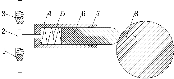
[0003] However, the plunger 6 of the existing plunger pump needs to be reset by the spring 5, and the long-term use of the spring 5 will cause deformation, resulting in a change in its displacement; in addition, the two built-in one-way valves are also springs. One-way check valve, long-term use will also cause its sensitivity to decrease due to the deformation of the internal spring

Method used


Image

  • Magnet type plunger pump
  • Magnet type plunger pump
  • Magnet type plunger pump

Examples


Embodiment Construction

[0013] The technical solutions in the embodiments of the present invention will be clearly and completely described below in conjunction with the accompanying drawings in the embodiments of the present invention. Obviously, the described embodiments are only a part of the embodiments of the present invention, rather than all the embodiments. Based on the embodiments of the present invention, all other embodiments obtained by those of ordinary skill in the art without creative work shall fall within the protection scope of the present invention.

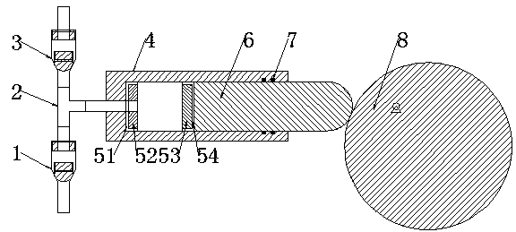
[0014] See figure 2 In the embodiment of the present invention, a magnet-type plunger pump includes a liquid inlet check valve 1, a three-way device 2, a liquid discharge check valve 3, a cylinder 4, a plunger 6, a sealing ring 7 and an eccentric 8 The fluid inlet and outlet of the cylinder 4 is provided with a cylinder hollow annular permanent magnet 52, and the cylinder hollow annular permanent magnet 52 and the cylinder 4 are provided...


PUM


Abstract

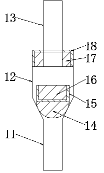
A magnet type plunger pump comprises a liquid inlet check valve, a tee joint device, a liquid outlet check valve, a cylinder body, a plunger, a seal ring and an eccentric wheel. An annular hollow permanent magnet of the cylinder body is arranged at a liquid access port of the cylinder body, and a hollow magnetic shield of the cylinder body is arranged between the cylinder body and the annular hollow permanent magnet of the cylinder body; an annular solid permanent magnet of the plunger is arranged at the inner end of the plunger, and a concave magnetic shield of the plunger is arranged between the plunger and the annular solid permanent magnet of the plunger; the annular solid permanent magnet of the plunger and the annular hollow permanent magnet of the cylinder body are arranged in opposite and repel mutually; the liquid inlet check valve and the liquid outlet check valve are both magnet type check valves. The magnet type plunger pump has the advantages that since reset springs in existing plunger pumps are replaced by the annular solid permanent magnet of the plunger and the annular hollow permanent magnet of the cylinder body which are arranged in opposite, service life of the plunger pump is remarkably prolonged, and flexibility of the plunger pump is evidently improved.

Description

Technical field [0001] The invention relates to a pump, in particular to a magnet type plunger pump. Background technique [0002] Plunger pump is an important device of hydraulic system, please refer to figure 1 , Is the schematic diagram of the existing plunger pump, and its structure includes the liquid inlet check valve 1, the three-way device 2, the liquid discharge check valve 3, the cylinder 4, the spring 5, the plunger 6, the sealing ring 7 and the eccentric wheel 8. A closed volume is formed between the plunger 6 and the cylinder 4, the eccentric 8 rotates one turn, the plunger 6 reciprocates up and down once, moves to the right to absorb oil, moves to the left to discharge oil, and the plunger pump discharges every revolution. The oil volume is called the displacement, and the displacement is only related to the structural parameters of the plunger pump. Therefore, the plunger pump has the advantages of high rated pressure, compact structure, high efficiency and conven...

Claims


Application Information

Patent Timeline
Patent Type & Authority Applications(China)
IPC IPC(8): F04B53/14F04B53/16F04B53/10
Inventor 贺旭辉张静
Owner 吉林省东元精密机械有限公司
Learn More