Flame detector with angle convenient to adjust

A flame detector and angle adjustment technology, which is applied in the field of flame detectors, can solve the problems of unfavorable flame detector detection performance and affecting the detection accuracy of flame detectors, and achieve excellent cooling effect, good angle adjustment performance, and ensure the effect of sensitivity

Active Publication Date: 2014-09-10
SICHUAN TIANWEI ELECTRONICS
View PDF5 Cites 6 Cited by
  • Summary
  • Abstract
  • Description
  • Claims
  • Application Information

AI Technical Summary

Problems solved by technology

[0004] In view of the above prior art, during installation or use, the fixed error of the fixed point and the position change of the fixed point during use will affect the detection accuracy of the flame detector, which is not conducive to ensuring the stable detection performance of the flame detector , the present invention provides a flame detector that is convenient for angle adjustment

Method used


Image

  • Flame detector with angle convenient to adjust

Examples


Embodiment 1

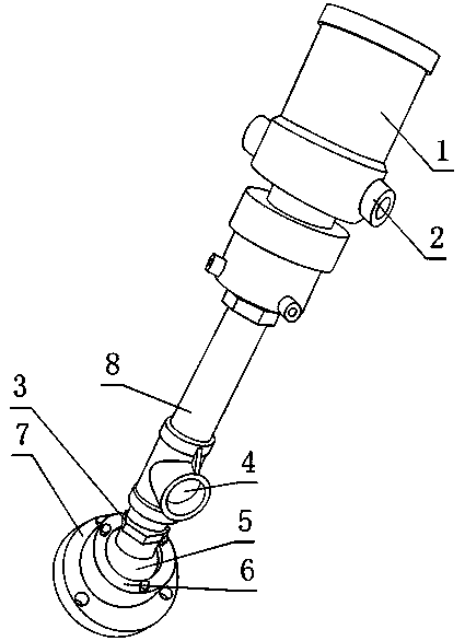
[0021] Such as figure 1 , a flame detector that is convenient for angle adjustment, including a detector body 1, a cooling part and a fixing part, the detector body 1 includes a casing, the casing is in a cylindrical structure, and the two ends of the cooling part are respectively connected to the detector On the opening end and the fixed part of the shell of the body 1;

[0022] The cooling part includes an air duct 8 and an air inlet 4 arranged at any position on the air duct 8;

[0023] The fixed part includes a mounting plate 7, a rolling ball 5 and a ball seat 6, the ball seat 6 is provided with a spherical cavity, the ball seat 6 and the mounting plate 7 are bolted or threaded, and the rolling ball 5 is located on the In the cavity, both ends of the air duct 8 are respectively fixedly connected with the opening end of the housing of the detector body 1 and the rolling ball 5, and the rolling ball 5 is limited between the ball seat 6 and the mounting plate 7;

[0024] T...

Embodiment 2

[0027] The present embodiment is further limited on the basis of embodiment 1, as figure 1 , in order to prevent the formation of cooling wind dead angle on the housing of the detector body 1, the number of the air outlets 2 is multiple.

Embodiment 3

[0029] The present embodiment is further limited on the basis of embodiment 1, as figure 1 , because the flame detector is generally installed inside the equipment or the outside is not easy to be affected by human factors, which makes it inconvenient to adjust the angle of the detector body 1. The angle of the main body 1 is adjusted. The air duct 8 is also provided with a braking part 3 for braking the rotation of the air duct 8. The braking part 3 is provided with at least a pair of parallel planes. The mutually parallel planes are clamping points of the brake part 3 by tools such as a wrench.


PUM


Abstract

The invention discloses a flame detector with the angle convenient to adjust. The flame detector comprises a detector body, a cooling portion and a fixing portion. The detector body comprises an outer shell, the outer shell is of a barrel-shaped structure, and the two ends of the cooling portion are connected to the open end of the outer shell of the detector body and the fixing portion respectively. The cooling portion comprises an air pipe and an air inlet formed in any position of the air pipe. The fixing portion comprises a mounting plate, a rolling ball and a ball seat, a ball-shaped cavity is formed in the ball seat, the ball seat is in bolted connection or threaded connection with the mounting plate, the rolling ball is located in the cavity, and the two ends of the air pipe are fixedly connected with the open end of the outer shell of the detector body and the rolling ball respectively. An air outlet is formed in the outer shell of the detector body. The flame detector is simple in structure, the detector body has the good angle adjusting performance relative to a monitoring point, and the angle can be conveniently adjusted in the mounting and using process of the flame detector. Meanwhile, the long-time sensitivity and the good cooling effect of the flame detector can be guaranteed through the structure of the flame detector.

Description

technical field [0001] The invention relates to a safety monitoring device for supervising flame conditions, in particular to a flame detector which is convenient for angle adjustment. Background technique [0002] At present, there are gaseous or solid combustibles in chemical plants, oil refineries, substations, industrial warehouses, and even common diesel generator rooms used as emergency power sources, people's living environments, whether it is numerous industrial control equipment or complex Living environment, if the fire is strictly monitored in these occasions, it will provide great protection for property protection and people's life safety. [0003] Flame detector, also known as photosensitive fire detector, is a fire detector used to respond to the light characteristics of fire, that is, to detect the light intensity of flame burning and the flicker frequency of flame. In the prior art, flame detection devices are generally in Infrared detectors are packaged in...

Claims


Application Information

Patent Timeline
Patent Type & Authority Applications(China)
IPC IPC(8): G01J1/04
Inventor 刘云黄成国汪小婷康美苓
Owner SICHUAN TIANWEI ELECTRONICS
Why Eureka
Try Eureka