Localizable electric wire guiding pulley

A technology of guiding pulleys and wires, applied in the directions of overhead lines/cable equipment, the use of reels/photosensitive drums, etc., can solve the problems of insecurity, rapid wire rewinding, and no braking device, and achieve low cost , the effect of simple structure

Inactive Publication Date: 2014-09-10
STATE GRID SICHUAN ELECTRIC POWER
View PDF6 Cites 2 Cited by
  • Summary
  • Abstract
  • Description
  • Claims
  • Application Information

AI Technical Summary

Problems solved by technology

[0002] The wire guide pulley is an important auxiliary equipment in the wire erection. The existing wire guide pulley does not have a brake device. The way to control the wire not to move during the erection process is mainly the pulling device at the beginning or the human pull to prevent the wire from moving. The above two There are unsafe factors in both methods. When the pulling device fails, for example, the pulling device stops and does not run, the wire will quickly retreat at this time, and the previous wire pulling operation needs to be re-operated, and the manual positioning will cause the operator to be in a state of doing work for a long time , and the general operators are working at high altitude, so it will cause harm to the safety of the operators

Method used


Image

  • Localizable electric wire guiding pulley
  • Localizable electric wire guiding pulley

Examples


Embodiment 1

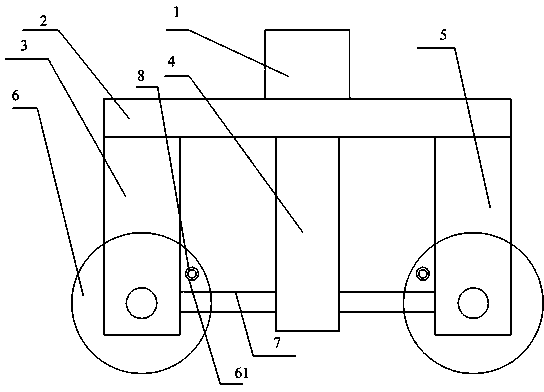
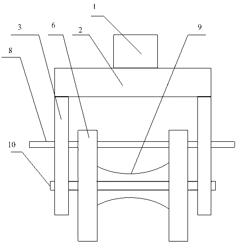
[0015] Such as Figure 1-Figure 2 shown.

[0016] Positionable wire guide pulley, including 2 pulley bodies, each pulley body is mainly composed of 2 chucks 6, 1 grooved roller 9, and 1 through shaft 10, and the 2 chucks 6 are respectively installed on the grooved roller 9 The two ends of the side, the through shaft 10 runs through the center of the chuck 6 and the center of the end face of the grooved roller 9, and the end faces of the two chucks 6 are provided with positioning through holes 61; it also includes a pulley frame body, which includes a hanging plate 1 , the lower side of the hanging plate 1 is connected with the main body block 2, and the lower side of the main body block is connected with 2 first splints 3, 2 middle limit splints 4, 2 second splints 5, and the 2 first splints 3 are respectively connected to the second splint On the two ends of the through shaft 10 of one pulley body, two second splints are respectively connected to the two ends of the through ...


PUM


Abstract

The invention discloses a localizable electric wire guiding pulley. The localizable electric wire guiding pulley comprises two pulley bodies and a pulley rack, wherein each pulley body mainly comprises two chucks, a groove-shaped roller and a through shaft; the two chucks of each pulley body are respectively arranged on side surfaces of two ends of the corresponding groove-shaped roller; each through shaft penetrates in the circle centers of the corresponding chucks and the circle centers of end surfaces of the corresponding groove-shaped roller; positioning through holes are formed in end surfaces of the two chucks of each pulley body; the pulley rack comprises a hanger plate; the lower side surface of the hanger plate is connected with a main body block; the lower side surface of the main body block is connected with two first clamping plates, two intermediate limiting clamping plates and two second clamping plates; the two first clamping plates are respectively connected to two ends of the through shaft of the first pulley body; the two second clamping plates are respectively connected to two ends of the through shaft of the second pulley body; the intermediate limiting clamping plates are respectively connected with the first clamping plates and the second clamping plates through connecting columns; and positioning columns are inserted in the positioning through holes. The guiding pulley can be located.

Description

technical field [0001] The invention relates to positionable wire guide pulleys in electrical equipment. Background technique [0002] The wire guide pulley is an important auxiliary equipment in the wire erection. The existing wire guide pulley does not have a brake device. The way to control the wire not to move during the erection process is mainly the pulling device at the beginning or the human pull to prevent the wire from moving. The above two There are unsafe factors in both methods. When the pulling device fails, for example, the pulling device stops and does not run, the wire will quickly retreat at this time, and the previous wire pulling operation needs to be re-operated, and the manual positioning will cause the operator to be in a state of doing work for a long time , and the general operator is working at high altitude, so it will cause harm to the safety of the operator. Contents of the invention [0003] The purpose of the present invention is to provide ...

Claims


Application Information

Patent Timeline
Patent Type & Authority Applications(China)
IPC IPC(8): H02G1/02H02G11/02
Inventor 阎召进杨天波于雷
Owner STATE GRID SICHUAN ELECTRIC POWER
Why Eureka
Try Eureka