Motion picture coding method and device
A coding method and moving image technology, applied in the field of moving image coding programs, can solve problems such as buffer underflow, achieve the effects of suppressing buffer underflow, reducing the amount of calculation, and improving image quality
- Summary
- Abstract
- Description
- Claims
- Application Information
AI Technical Summary
Problems solved by technology
Method used
Image
Examples
Embodiment 1
[0070] image 3 Fig. 1 is an apparatus configuration diagram related to Embodiment 1 of the present invention. In addition, regarding other examples, the basic device structure is the same as that of the first example.
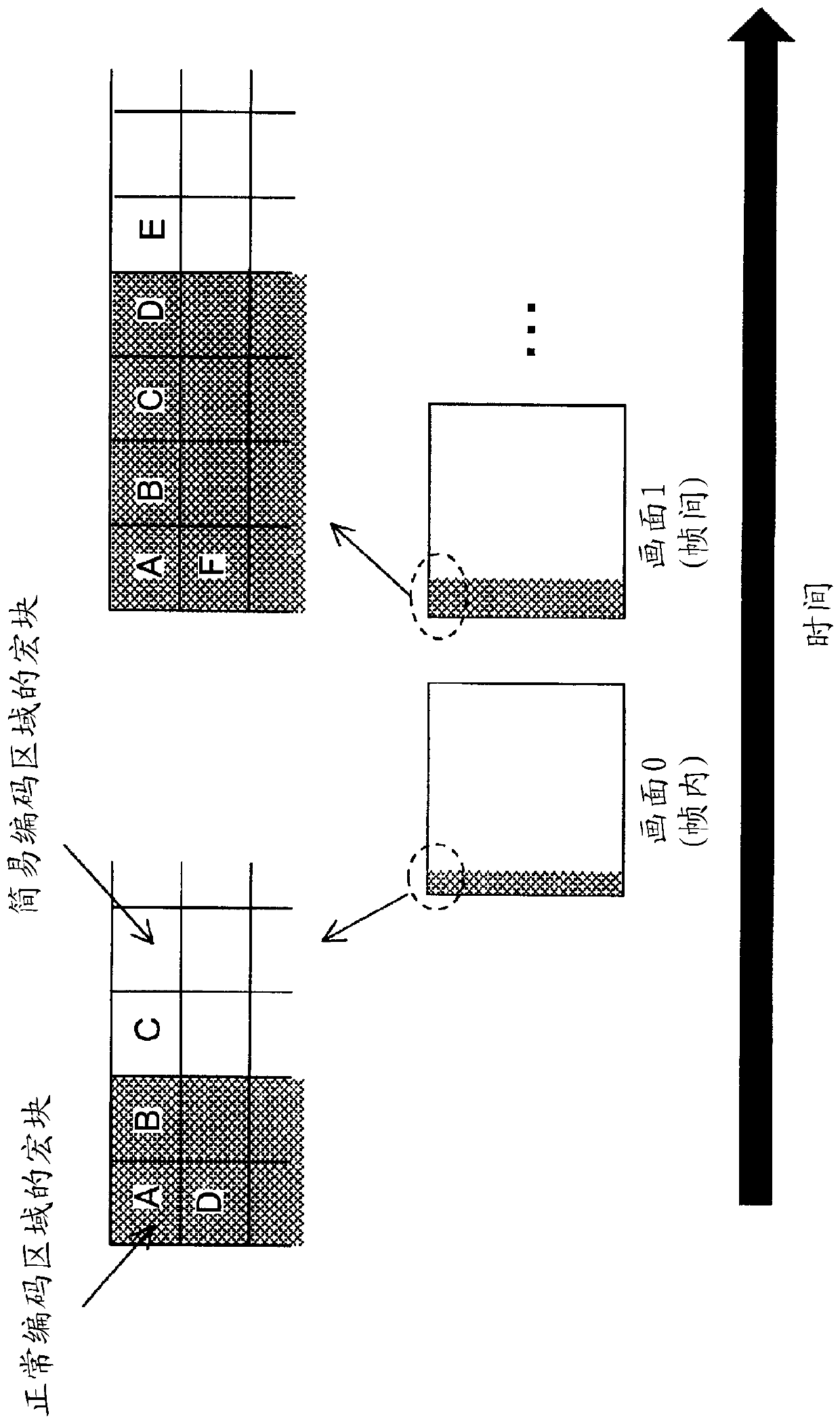
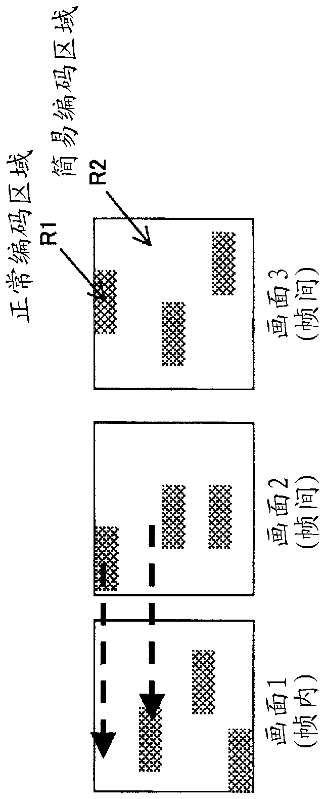
[0071] The normal encoding area setting unit 101 determines which macroblock is to be normally encoded based on the picture number, and outputs this information to the block encoding control unit 102 as normal encoding area information. In the first embodiment, as described above, the normal coding area is enlarged in columns of 2 macroblocks per picture. In addition, only the first picture (the picture number is 0) becomes an intra picture. Therefore, starting from the picture whose picture number is 40, normal encoding is performed in all macroblocks.
[0072] The block encoding control unit 102 inputs a picture, and further inputs normal encoding area information corresponding to the picture. Furthermore, in screen scanning order, if the macroblock of t...
Embodiment 2
[0083] Although the basic flow of the second embodiment is the same as that of the first embodiment, the operation of the normal encoding unit 103 is somewhat different. Specifically, the operation at the time of inter-frame encoding of a block is different.
[0084] In a general H.264 coder, inter-coding may be performed with reference to the simplified coding region because the normal coding region and the simplified coding region in the reference picture are not considered during the dynamic search during intercoding of a block. Generally, in a dynamic search, a prescribed search range centered on a prescribed search center is searched. exist Figure 5 The example is shown in (A). In the H.264 coder, there is a case where the predictive vector is used as the search center. In this case, the search range is included in the simplified coding area of the reference picture, and since this block is coded with reference to the simplified coding area, a Lots of prediction res...
Embodiment 3
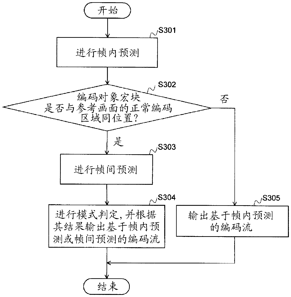
[0088] Although the basic flow of the third embodiment is the same as that of the first embodiment, the operation of the normal encoding unit 103 is slightly different. Specifically, the coding operation of macroblocks co-located with the simplified coding region of the reference picture among the macroblocks of the normal coding region of the coding target picture is different. Such a macroblock, for example, is equivalent to figure 2 Macroblocks C and D in picture 1 of .
[0089] In encoding of a macroblock, mode determination is generally performed. In mode determination, the rate-distortion cost after intra-coding is compared with the rate-distortion cost after inter-coding, and an encoding method that minimizes the rate-distortion cost is selected.
[0090] exist Figure 7 A flowchart of Example 3 is shown in . First, perform intra prediction (S301). In the normal coding unit 103 of the third embodiment, it is determined whether the current macroblock is co-located ...
PUM
 Abstract
Description
Claims
Application Information
 - R&D
- Intellectual Property
- Life Sciences
- Materials
- Tech Scout
- Unparalleled Data Quality
- Higher Quality Content
- 60% Fewer Hallucinations
Browse by: Latest US Patents, China's latest patents, Technical Efficacy Thesaurus, Application Domain, Technology Topic, Popular Technical Reports.
© 2025 PatSnap. All rights reserved.Legal|Privacy policy|Modern Slavery Act Transparency Statement|Sitemap|About US| Contact US: help@patsnap.com


