Video encoding method, device, and program

A coding method and a moving image technology, applied in the field of moving image coding programs, can solve problems such as buffer underflow, and achieve the effects of suppressing buffer underflow, reducing the amount of computation, and improving image quality

Active Publication Date: 2014-09-10
NIPPON TELEGRAPH & TELEPHONE CORP
View PDF4 Cites 1 Cited by
  • Summary
  • Abstract
  • Description
  • Claims
  • Application Information

AI Technical Summary

Problems solved by technology

For this reason, buffer underflow (buffer underflow) is prone to occur in the intra

Method used


Image

  • Video encoding method, device, and program
  • Video encoding method, device, and program
  • Video encoding method, device, and program

Examples


Example Embodiment

[0069] [Example 1]

[0070] image 3 It is a configuration diagram of an apparatus related to Example 1 of the present invention. In addition, regarding other embodiments, the basic device structure is the same as that of the first embodiment.

[0071] The normal coding region setting unit 101 determines which macroblock is a block to be normally coded based on the picture number, and outputs this information as normal coding region information to the block coding control unit 102. In the first embodiment, as described above, the normal coding area is enlarged in two macroblock columns per picture. In addition, only the first screen (the screen number is 0) becomes an intra screen. Therefore, starting from the picture whose picture number is 40, normal coding is performed in all macroblocks.

[0072] The block coding control unit 102 inputs a picture, and further inputs normal coding region information corresponding to the picture. Furthermore, in the order of screen scanning, if...

Example Embodiment

[0082] [Example 2]

[0083] Although the basic flow of the second embodiment is the same as that of the first embodiment, the operation of the normal encoding unit 103 is slightly different. Specifically, the operations during inter-coding of blocks are different.

[0084] In a general H.264 encoder, in the dynamic search during inter-coding of blocks, since the normal coding area and the simple coding area in the reference picture are not considered, there are cases where the simple coding area is referred to for inter-coding. Generally, in a dynamic search, the search is performed in a specified search range centered on a specified search center. in Figure 5 This example is shown in (A). In the H.264 encoder, there is a case where the prediction vector is used as the search center. In this case, the search range is included in the simple coding area of ​​the reference picture. For this block, since the simple coding area is referenced for encoding, it is generated Many predic...

Example Embodiment

[0087] [Example 3]

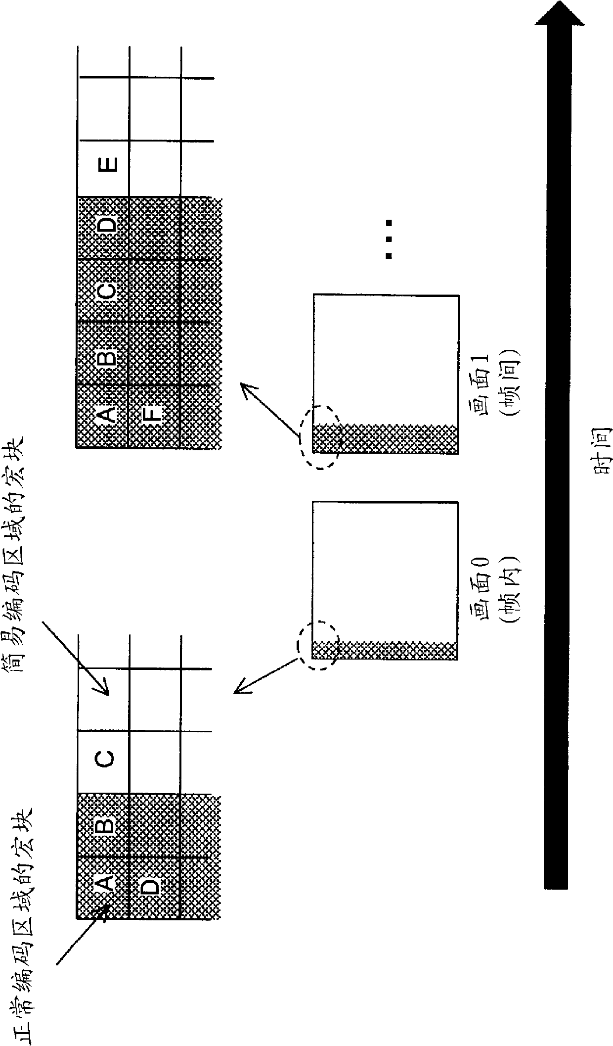
[0088] Although the basic flow of the third embodiment is the same as that of the first embodiment, the operation of the normal encoding unit 103 is slightly different. Specifically, among the macroblocks in the normal coding region of the coding target picture, the coding operation of the macroblock at the same position as the simple coding region of the reference picture is different. Such a macro block, for example, is equivalent to figure 2 Macroblocks C and D in picture 1.

[0089] In the coding of macroblocks, mode determination is generally performed. In the mode determination, the rate-distortion cost in the case of intra-coding is compared with the rate-distortion cost in the case of inter-coding, and the coding method that minimizes the rate-distortion cost is selected.
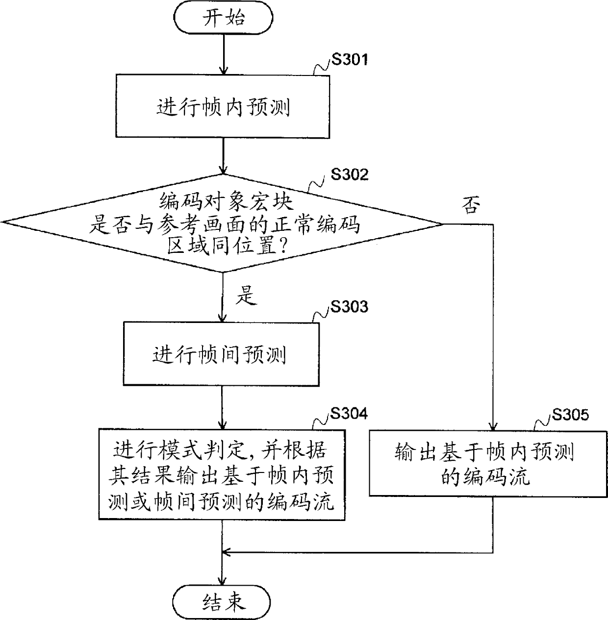
[0090] in Figure 7 The flowchart of Example 3 is shown in. First, intra prediction is performed (S301). In the normal coding unit 103 of the third embodiment, it is determined wh...


PUM


Abstract

In an intra-picture, a prescribed region is set to a normal encoding region, and a region other than the prescribed region is set to a simplified encoding region. In a successive picture, the normal encoding region is set to a larger region which encompasses the normal encoding region of the preceding picture, and the region other than said region is set to the simplified encoding region. In each picture, normal encoding is carried out in the normal encoding region block, and simplified encoding is carried out in the simplified encoding region block, said simplified encoding being encoding wherein the resulting encoding volume and computation volume are smaller than the normal encoding.

Description

technical field [0001] This application claims priority based on Japanese Patent Application No. 2012-014062 for which it applied in Japan on January 26, 2012, and uses the content here. The present invention relates to a moving picture coding method, a moving picture coding device, and a moving picture coding program for switching between a normal coding method and a simple coding method which generates a small amount of coding and calculation and encodes a moving picture. Background technique [0002] In video encoding in two-way communication, the size of the virtual buffer is made very small in order to achieve low latency. For this reason, buffer underflow (buffer underflow) is likely to occur in the intra picture at the start of encoding, the scene change, and the inter picture thereafter. [0003] In such a situation, by applying, for example, the technique described in Patent Document 1, the possibility of buffer underflow can be reduced at the time of intra picture...

Claims


Application Information

Patent Timeline
IPC IPC(8): H04N19/17H04N19/127H04N19/115H04N19/103
CPCH04N19/14H04N19/00369H04N19/146H04N19/172H04N19/0006H04N19/00103H04N19/18H04N19/55H04N19/00018H04N19/00169H04N19/196H04N19/17H04N19/127H04N19/00024H04N19/115H04N19/15H04N19/132H04N19/197H04N19/107H04N19/0026H04N19/103H04N19/105H04N19/00296H04N19/00266H04N19/126H04N19/124H04N19/152H04N19/167H04N19/176
Inventor 北原正树清水淳中村健京地清介小野尚纪
Owner NIPPON TELEGRAPH & TELEPHONE CORP
Why Eureka
Try Eureka