
Methods of manufacture and use of energized ophthalmic devices having electrical storage mode

An ophthalmic device and storage mode technology, which can be used in ophthalmic treatment, applications, home appliances, etc., and can solve problems such as current leakage

Inactive Publication Date: 2014-09-17
JOHNSON & JOHNSON VISION CARE INC
View PDF13 Cites 1 Cited by
  • Summary
  • Abstract
  • Description
  • Claims
  • Application Information

AI Technical Summary

Problems solved by technology

Incorporating energization elements into ophthalmic devices also introduces additional current leakage issues, since solutions to leakage do not rely on direct electrical contact

Method used


Image

  • Methods of manufacture and use of energized ophthalmic devices having electrical storage mode
  • Methods of manufacture and use of energized ophthalmic devices having electrical storage mode
  • Methods of manufacture and use of energized ophthalmic devices having electrical storage mode

Examples


Embodiment Construction

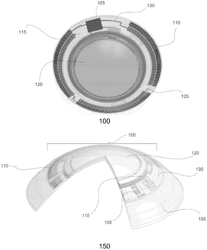
[0024] The present invention relates to an energized ophthalmic device having a storage mode that conserves energy by reducing current leakage when the ophthalmic device is not in use, and includes methods of manufacture and methods of use. Embodiments of the present invention will be described in detail in the following sections. Both the preferred and alternative embodiments described herein are exemplary embodiments only, and it is to be understood that alterations, modifications and alterations thereof may be apparent to those skilled in the art. Therefore, it should be understood that the exemplary embodiments do not limit the scope of the invention upon which it is based.

[0025] The incorporated battery pack may have a low drain state or storage mode to maintain sufficient power to operate while the ophthalmic device is in use. A user of the ophthalmic device is then able to activate or wake up the battery pack and / or load circuitry. Power supplies with storage modes...


PUM


Abstract

This invention discloses methods of manufacture and use of an energized ophthalmicdevice with an incorporated Storage Mode for a power source, the method of manufacturing said device, and a method of activation that may restore the power source to an operational mode.

Description

[0001] Related Patent Applications [0002] This patent application, as a partial patent application continuation, claims priority over patent application No. 13 / 781,494, which was filed on February 28, 2013 and is named Methods And Apparatus To Form Electronic Circuitry on Ophthalmic Devices ( Method and Apparatus for Forming Electronic Circuitry on Ophthalmic Devices), which claims priority over the filed on February 28, 2012, entitled Methods And Apparatus To Form Electronic Circuitry on Ophthalmic Devices (on Ophthalmic Devices Provisional Patent Application No. 61 / 604,206 for Methods and Apparatus for Forming Electronic Circuits. technical field [0003] The present disclosure describes methods of making and using an energized ophthalmic device having a Media Insert with a Storage Mode, and more particularly, wherein the Media Insert incorporates a switching mechanism that can be placed in a Storage Mode and an Operating Mode. Background technique [0004] Traditionall...

Claims


Application Information

Patent Timeline
Patent Type & Authority Applications(China)
IPC IPC(8): A61F9/00
CPCG02C7/083G02C7/04B29D11/00
Inventor R.B.普格D.B.奧特斯A.托纳J.D.里亚尔S.R.汉弗莱斯F.A.弗里特施C.希格哈姆
Owner JOHNSON & JOHNSON VISION CARE INC
Learn More