Head with Extended Collar

A drum head and collar technology, applied in musical instruments, percussion instruments, instruments, etc., can solve problems such as reducing output and achieve the effect of improving tuning

Active Publication Date: 2017-07-04
D'ADDARIO
View PDF8 Cites 0 Cited by
  • Summary
  • Abstract
  • Description
  • Claims
  • Application Information

AI Technical Summary

Problems solved by technology

This is a difficult task with many complex variables that can lead to lower yields in order to meet the desired quality threshold

Method used


Image

  • Head with Extended Collar
  • Head with Extended Collar
  • Head with Extended Collar

Examples


Embodiment Construction

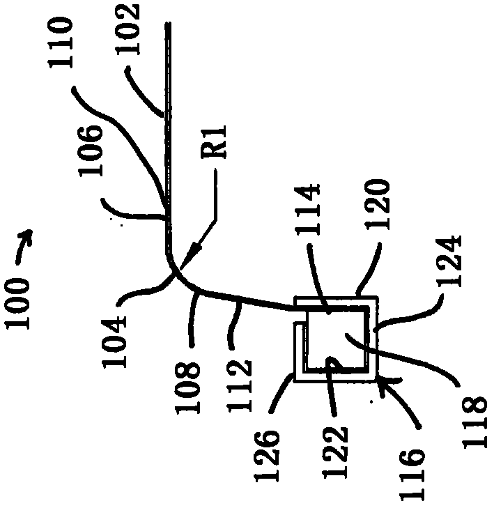
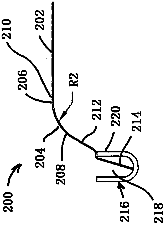
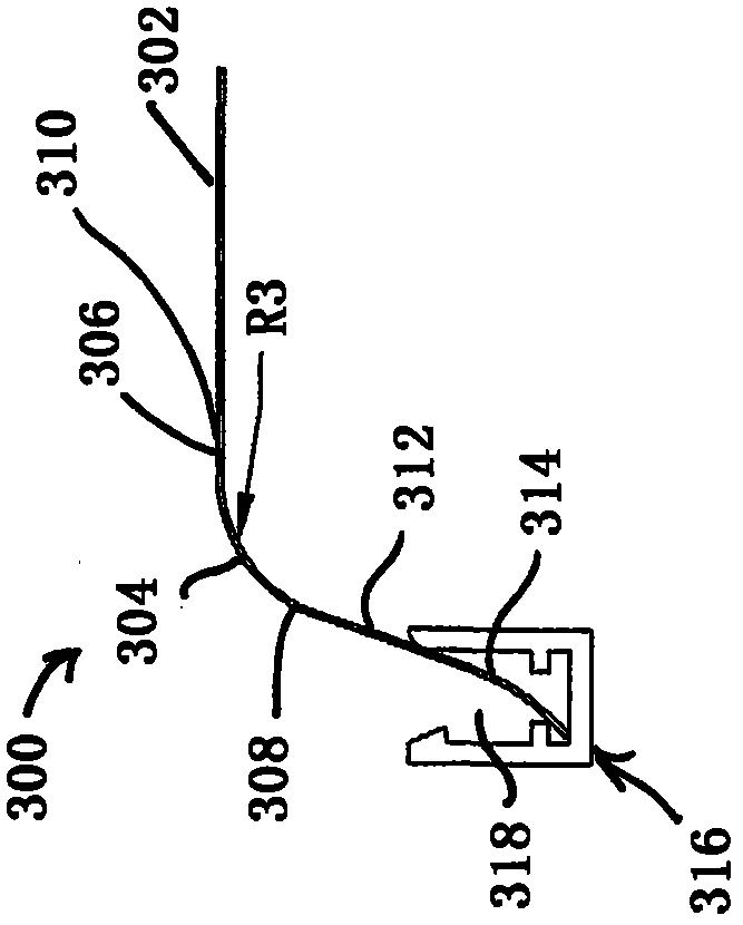
[0019] Figure 1-4 Shows a cross-section of one side of a prior art drumhead having a differently shaped curved collar extending generally outward and downward from the central play area to the hoop. It should be understood that drums have different sizes, generally dictated by the nominal diameter of the drum shell, and likewise, drum heads have various corresponding dimensions dictated by the diameter of the drum shell. For convenience, the present disclosure will only focus on a 14 inch nominal diameter head, but it should be understood that similar principles may apply to drums having other diameters.

[0020] exist figure 1 In the embodiment of the present invention, the head 100 has a flat striking area 102 with a diameter of 13.69 inches. Collar 104 has a convex curved region having an upper end 106 and a lower end 108 having a radius R1 of approximately 0.156 inches, wherein the upper end has a tangential transition to the flat strike region 110; and a skirt region...


PUM


Abstract

A drumhead comprising a circular membrane having a flat central play region, a collar extending outwardly and downwardly from the play region, and an outer edge region extending from the collar. A hoop defines a circular channel in which the outer edge region of the membrane is retained. The collar has a convexly curved region having upper and lower ends spanning an included angle, with the upper end transitioning tangentially into the play region and a frustoconical skirt region flaring outwardly from the lower end of the curved region and transitioning into the outer edge area. The included angle of the convexly curved region is about 90 deg., and the skirt and outer edge region of the membrane frustoconically extend from the lower end of the curved region to the channel of the hoop, at a substantially uniform angle in the range of about 10 to 30 deg.

Description

Background technique [0001] The invention relates to musical drum heads. The contour of the collar on the drumhead is a key design consideration. The diameters of many drums of nominal standard size are not actually the same and, as a result, the bearing edges (the part of the drum shell that contacts the bottom surface of the drum head) also vary widely in diameter, angle and precision. [0002] Some desirable vintage drums require a slightly larger diameter head so that the bearing edge does not interface with the curved or formed collar area of ​​the head. The drumhead can be tuned faster, better and easier if the bearing edge is in contact with the flat face of the drumhead membrane. [0003] Modern drumheads are finely tuned through a combination of heat, pressure, and time. This is a difficult task with many complex variables that can result in lower yields in order to meet desired quality thresholds. Contents of the invention [0004] The present invention improve...

Claims


Application Information

Patent Timeline
Patent Type & Authority Patents(China)
IPC IPC(8): G10D13/02
CPCG10D13/02G10D13/20
Inventor 史蒂文·T·默里理查德·K·德拉姆
Owner D'ADDARIO
Why Eureka
Try Eureka