
Light-emitting device

一种发光装置、发光区的技术,应用在照明装置、照明装置的零部件、用于改变发射光的光谱特性的光学元件等方向,能够解决显示画面被截断或亮暗线条明显不易解决等问题,达到佳显示品质的效果

Active Publication Date: 2014-09-17
AU OPTRONICS CORP
View PDF7 Cites 8 Cited by
  • Summary
  • Abstract
  • Description
  • Claims
  • Application Information

AI Technical Summary

Problems solved by technology

However, in a display panel where the display screen of a handheld device such as a mobile phone can be rotated according to the needs of the user, the above-mentioned penetrating regions distributed in stripes will have various changes, resulting in truncated display screens or obvious bright and dark lines. Condition is obvious and not easy to resolve

Method used


Image

  • Light-emitting device
  • Light-emitting device
  • Light-emitting device

Examples


Embodiment Construction

[0058] Below in conjunction with accompanying drawing, structural principle and working principle of the present invention are specifically described:

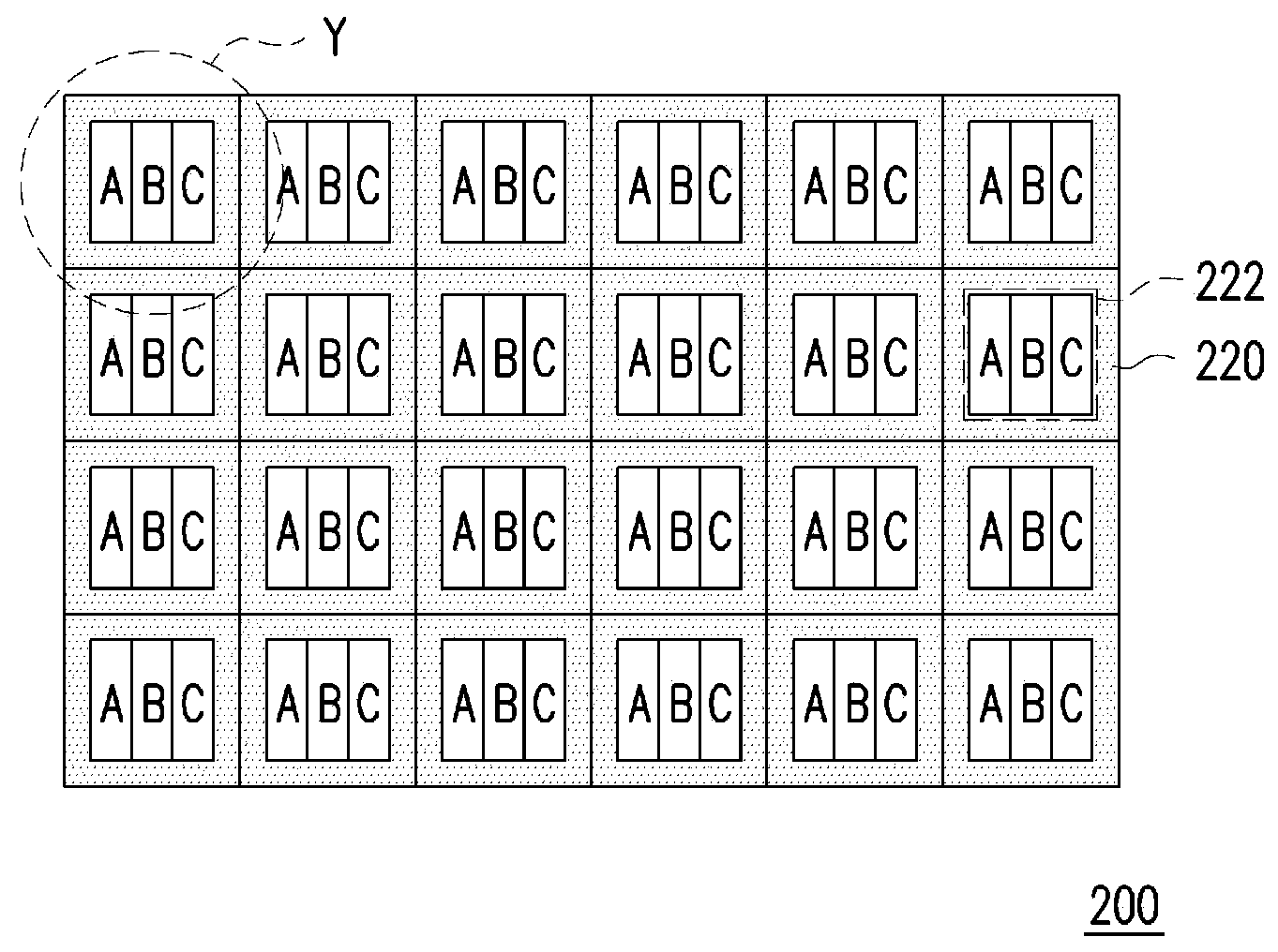
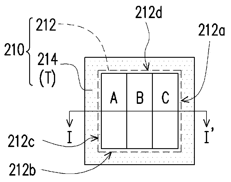
[0059] Figure 2A is a top view of a light emitting device according to an embodiment of the present invention, Figure 2B for Figure 2A An enlarged schematic view of region Y of the light-emitting device, and Figure 2C for along Figure 2B The schematic cross-sectional view of the I-I' line of the light-emitting device. Please also refer to Figure 2A to Figure 2C , the light emitting device 200 includes a plurality of units 210 . The units 210 are, for example, arranged in an array. In this embodiment, it is taken as an example that the units 210 are arranged in a 6×4 matrix, but the present invention is not limited thereto.

[0060]Each unit 210 includes a light emitting area 212 and a penetrating area 214 , wherein in at least one unit 210 , the penetrating area 214 surrounds at least two sides 212 a , 212 b , 212...


PUM


Abstract

A light-emitting device comprises a plurality of units. Each unit comprises a light-emitting region and a penetrating region. In at least one unit, the penetrating region surrounds at least two side edges of the light-emitting region. As in the units of the device, the penetrating regions are designed to surround at least two side edges of the light-emitting regions, the penetrating regions and the light-emitting regions are arranged alternately, and the penetrating regions are evenly distributed in the device. Therefore, the device can emit light uniformly when being used as a light source. When the device is used as a display panel, a display image can be prevented from being cutting off or significant bright and dark lines can be avoided, so that the display panel has good display quality.

Description

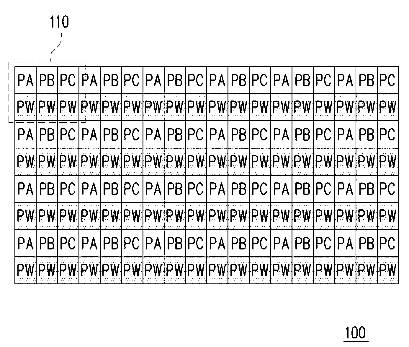
technical field [0001] The invention relates to a light-emitting device, in particular to a light-emitting device that can be used as a light source for uniform light emission or a display panel with good penetrating image quality. Background technique [0002] A transparent display panel (Transparent Display) means that the display panel itself has a certain degree of penetration, and can clearly display the background behind the panel. Transparent display panels are suitable for a variety of applications such as building windows, car windows and shop windows. In addition to the original transparent display function, it also has the potential to be used as an information display panel in the future, so it has attracted market attention. [0003] figure 1 It is a schematic diagram of a prior art transparent display panel. Please refer to figure 1 , the display panel 100 is an Active-Matrix Organic Light-Emitting Diode (AMOLED) transparent display panel, which includes a ...

Claims


Application Information

Patent Timeline
Patent Type & Authority Applications(China)
IPC IPC(8): H01L27/32H01L51/52
CPCH10K59/353H10K59/88F21V9/08
Inventor 李佳桦杨学炎吴璧丞
Owner AU OPTRONICS CORP
Learn More