
Undisturbed switching mechanism of voltage-stabilization electricity-saving device

A technology of non-disturbance switching and power-saving device, which is used in output power conversion devices, conversion equipment that can be converted to DC without intermediate conversion, electrical components, etc. Open circuit state and other problems to achieve the effect of improving stability, prolonging service life and increasing capacity

Inactive Publication Date: 2014-09-17
ANHUI GEMINI ELECTRIC TECH
View PDF6 Cites 60 Cited by
  • Summary
  • Abstract
  • Description
  • Claims
  • Application Information

AI Technical Summary

Problems solved by technology

[0004] Its shortcoming is that this device needs to switch the thyristor continuously according to the change of the input or output voltage. At the moment of switching, the compensation transformer is in a short-term open state
It is precisely because of the short-term open-circuit state of the compensation transformer that it will bring a lot of impact and noise when switching. Therefore, it is difficult for the conventional non-contact switch switching technology to be truly non-disturbed when used in voltage stabilizing and energy-saving devices. It may even cause damage to the SCR
The commonly used solution is to increase the capacity and withstand voltage level of the thyristor, which greatly increases the cost on the one hand, and limits the installed capacity of the voltage stabilizing and power saving device on the other hand.

Method used


Image

  • Undisturbed switching mechanism of voltage-stabilization electricity-saving device
  • Undisturbed switching mechanism of voltage-stabilization electricity-saving device

Examples


Embodiment Construction

[0011] The present invention will be further described below in conjunction with the accompanying drawings.

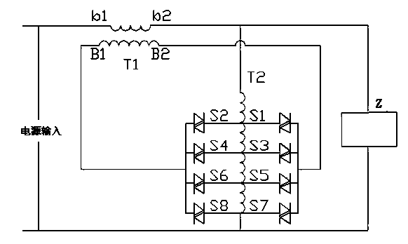
[0012] Such as figure 1 As shown, the existing compensating voltage stabilizing power saving device is composed of a compensating transformer T1, a voltage regulating transformer T2, and thyristors S1 to S8. Its working principle is: by turning on and off different combinations of thyristors S1 to S8, that is, controlling the conduction of the corresponding thyristors in the voltage regulating circuit, thereby changing the direction and magnitude of the voltage compensated by the compensation transformer T1, and finally realizing the output The voltage is stable within the desired range.

[0013] Its shortcoming is that the device needs to continuously switch the thyristor according to the change of the input or output voltage, and at the moment of switching, the compensation transformer is in a short-term open state. It is precisely because of the short-term open-ci...


PUM


Abstract

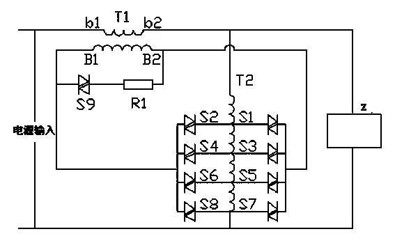
The invention relates to a voltage-stabilization electricity-saving device, and particularly relates to an undisturbed switching mechanism of the voltage-stabilization electricity-saving device. The undisturbed switching mechanism comprises a power source, a compensation transformer connected with the power source and a voltage-regulating transformer connected in series between the power source and the compensation transformer. The undisturbed switching mechanism further comprises a load connected in parallel at the two ends of the compensation transformer, and a bidirectional thyristor mechanism connected in series with the compensation transformer. The undisturbed switching mechanism is characterized in that the undisturbed switching mechanism further comprises a series circuit formed by a resistor and a bidirectional thyristor, wherein the series circuit is connected in parallel to the secondary coil of the compensation transformer. Compared with the prior art, the undisturbed switching mechanism in the invention solves the problem of strong impact generated during thyristor switching, and obvious noise cannot be generated during switching, so that the stability of the system is greatly improved, the service life of the thyristor is prolonged, and the capacity of the intelligent voltage-stabilization electricity-saving device can be greatly increased when the thyristors with same capacity and withstand voltage level are adopted.

Description

technical field [0001] The invention relates to a voltage stabilizing and power saving device, in particular to a non-disturbance switching mechanism of the voltage stabilizing and power saving device. Background technique [0002] The so-called non-disturbance switching technology usually uses a non-contact static switch for switching. Due to the extremely short switching time, it can often achieve basically no disturbance in most occasions. At present, in the existing self-coupling voltage regulation and compensation intelligent voltage stabilization and power saving devices, the technical means to realize voltage stabilization are mostly realized by controlling the switching off of the thyristor. [0003] Such as figure 1 As shown, the existing compensating voltage stabilizing power saving device is composed of a compensating transformer T1, a voltage regulating transformer T2, and thyristors S1 to S8. By turning on and off different combinations of thyristors S1 to S8,...

Claims


Application Information

Patent Timeline
IPC IPC(8): H02M5/257H02M5/12
Inventor 程树林徐美松
Owner ANHUI GEMINI ELECTRIC TECH
Learn More