Rail wheel

A wheel and track technology, applied in the field of rail wheels, can solve the problems of cost and difficulty, achieve the effect of simple and effective disassembly, and reduce friction

Active Publication Date: 2014-09-17
VOITH PATENT GMBH
View PDF6 Cites 0 Cited by
  • Summary
  • Abstract
  • Description
  • Claims
  • Application Information

AI Technical Summary

Problems solved by technology

This is extremely costly and difficult when dismounting is necessary, especially in the case of rail wheels for low-frame vehicles in which the overall installation space is limited

Method used


Image

  • Rail wheel

Examples


Embodiment Construction

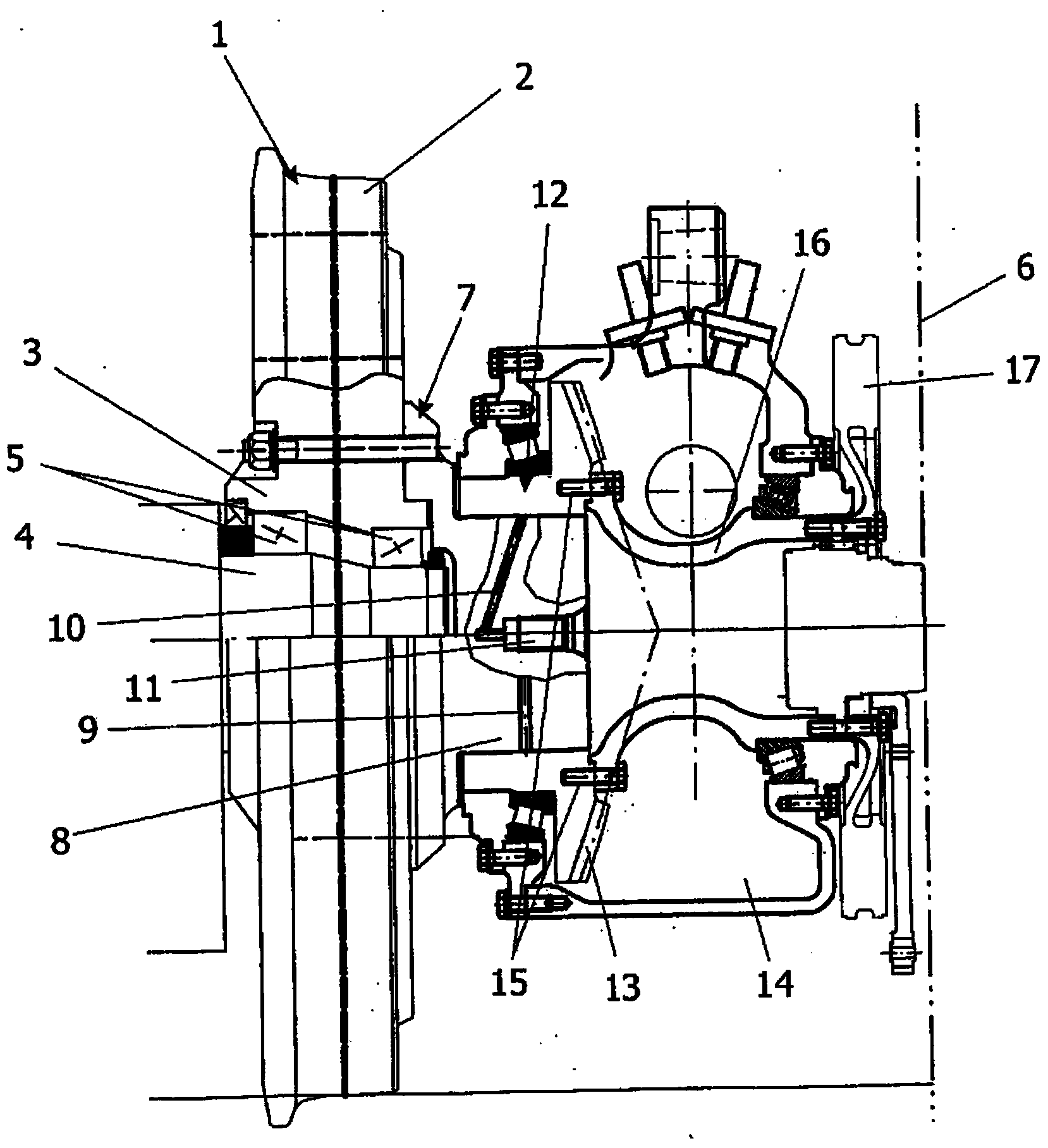
[0017] A rail wheel 1 can be identified in the drawings. The rail wheel 1 has a rim 2 and a hub 3 . The rim and hub are connected to one another via webs which cannot be clearly identified in the view shown here. The rail wheel 1 can be constructed in one piece or in multiple pieces. The hub 3 of the rail wheel 1 runs around a fixed axle 4 . The individual bearings 5 ​​for the hub 3 are schematically shown. The rail wheel 1 is mounted on the axle 4 from the right in the view in the drawing and should also remain accessible from this right for future installation and maintenance work. The right side here is the side that is accessible from the side of the rail vehicle that is not shown. The two-dot dash line provided with the reference numeral 6 indicates the lateral delimitation of the rail vehicle.

[0018] Now, in the construction of the rail wheel 1 shown here, the intermediate element 7 is connected to the rail wheel 1 in a rotationally fixed manner. For this purpose...


PUM


Abstract

The invention relates to a rail wheel (1) having a wheel hub (3) that revolves on a fixed shaft (4), and an intermediate element (7) detachably connected to the wheel hub for rotation therewith, wherein a hollow shaft (12) is pressed onto the intermediate element for rotation therewith, and wherein the hollow shaft pressed onto the intermediate element forms an oil press fit with the intermediate element, wherein the hollow shaft is connected to a transmission element (13) for rotation therewith in order to transmit a torque to the wheel hub, and the hollow shaft is at least indirectly connected to at least one further component (17) for rotation therewith in order to transmit a torque to the wheel hub.

Description

technical field [0001] The invention relates to a rail wheel of the type defined in detail in the preamble of claim 1 . Background technique [0002] Rail wheels are known from the prior art. A distinction is usually made here between driven rail wheels and non-driven rail wheels. Rail wheels that run together without a drive are often referred to as idlers. Especially in the case of driven rail wheels, the rail wheel has to be connected to a transmission unit and / or a motor-like drive in order to transmit the torque. Furthermore, further components for torque transmission, such as brake discs, should be connectable to the rail wheel. In order to achieve all of the above, it is common in the prior art to realize the coupling to the transmission on one side of the rail wheel, for example the brake side, and on the other side. This is extremely costly and difficult when dismounting is necessary, especially in the case of rail wheels for low-frame vehicles in which the over...

Claims


Application Information

Patent Timeline
Patent Type & Authority Applications(China)
IPC IPC(8): B61F3/16
CPCB61F3/16B61C9/52
Inventor 伯恩哈德·赫格恩里克·卢克阿莱曼
Owner VOITH PATENT GMBH
Why Eureka
Try Eureka