Sampling bag for laparoscopic surgery

The technology of a specimen bag and laparoscope, which is applied in the field of medical devices, can solve the problems of dropping the specimen bag into the abdominal cavity, operation failure, difficulty, etc., and achieve the effect of convenient and quick removal process.

Inactive Publication Date: 2014-09-24
THE FIRST AFFILIATED HOSPITAL OF HENAN UNIV OF SCI & TECH
View PDF5 Cites 2 Cited by
  • Summary
  • Abstract
  • Description
  • Claims
  • Application Information

AI Technical Summary

Problems solved by technology

[0002] In laparoscopic surgery, instruments are inserted into the abdominal cavity through a 5-10mm diameter cannula placed on the abdominal wall. Small specimens such as the excised appendix and biopsy specimens are generally taken out through the small incision where the 10mm diameter cannula is placed, without making another incision. When taking out the specimen, it needs to be put into the specimen bag to avoid falling into the abdominal cavity and making it difficult to find, and to avoid contaminating the small incision on the abdominal wall. The common specimen bag currently used is inserted into the abdominal cavity through a cannula and filled with small specimens. It is carried out under laparoscopic monitoring, so it is necessary to replace the sleeve or observation hole when taking it out, or align the adjacent sleeve with an instrument that holds the specimen bag. The operation is cumbersome and difficult, and it is easy to cause the specimen bag to rupture and the specimen to fall. , or cause damage to the abdominal organs. When the specimen is loaded and taken out, it is necessary to repeatedly clamp the mouth of the bag with laparoscopic operating instruments. During the process of taking the specimen out of the abdominal cavity, the specimen bag will fall into the abdominal cavity if one is not careful, or even The specimen slipped out of the bag, causing the operation to fail

Method used


Image

  • Sampling bag for laparoscopic surgery
  • Sampling bag for laparoscopic surgery
  • Sampling bag for laparoscopic surgery

Examples


Embodiment Construction

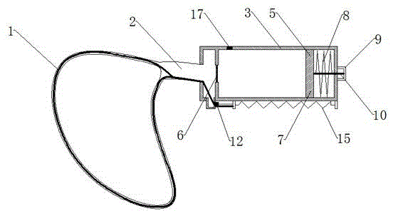
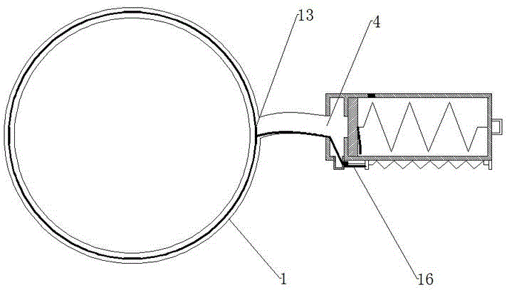
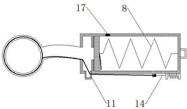
[0012] As shown in the figure: a specimen bag for laparoscopic surgery, including a bag body 1 and a trachea 2, the bag opening of the bag body 1 is a double-layer structure composed of an outer layer and an inner layer, and the outer layer and the inner layer An inflatable cavity is formed between them, and the inflatable cavity communicates with the trachea 2, and the other end of the trachea 2 is connected with an inflation and deflation control device. The inflation and deflation control device includes a cylindrical valve body 3, the valve body 3 has an internal cavity, one end of the valve body 3 is a closed end, and the other end of the valve body 3 has an inflation hole 4, the air pipe 2 and the valve The gas filling holes 4 of the body 3 are connected. A baffle 5 is arranged in the cavity of the valve body 3, and the baffle 5 is arranged close to one end of the valve body 3 having the air hole 4, and the baffle 5 divides the cavity of the valve body 3 into two parts. ...


PUM


Abstract

The invention relates to a sampling bag for a laparoscopic surgery. A bag opening of a bag body has a double-layer structure consisting of an outer layer and an inner layer, and an inflatable cavity is communicated with an air pipe, wherein an inflation and deflation control device is connected to the other end of the air pipe, and comprises a valve body; an inflation hole communicated with the air pipe is formed in one end of the valve body; a baffle plate, a piston and a spring I are arranged in a cavity of the valve body; the baffle plate divides the cavity of the valve body into two parts; a through hole is formed in the central position of the baffle plate; an airtight thin film is arranged at the through hole; the piston is arranged in the cavity between the baffle plate and the sealed end of the valve body. The sampling bag is used for the laparoscopic surgery, and is placed in an abdominal cavity during the surgery, and the bag opening of the sampling bag can be automatically opened, and is automatically tightened after a sample is placed, so that the whole sample taking process is convenient and rapid.

Description

technical field [0001] The invention relates to the technical field of medical instruments, in particular to a specimen-taking bag for laparoscopic surgery. Background technique [0002] In laparoscopic surgery, instruments are inserted into the abdominal cavity through a 5-10mm diameter cannula placed on the abdominal wall. Small specimens such as the excised appendix and biopsy specimens are generally taken out through the small incision where the 10mm diameter cannula is placed, without making another incision. When taking out the specimen, it needs to be put into the specimen bag to avoid falling into the abdominal cavity and making it difficult to find, and to avoid contaminating the small incision on the abdominal wall. The common specimen bag currently used is inserted into the abdominal cavity through a cannula and filled with small specimens. It is carried out under laparoscopic monitoring, so it is necessary to replace the sleeve or observation hole when taking it ...

Claims


Application Information

Patent Timeline
IPC IPC(8): A61B10/04
Inventor 师占红
Owner THE FIRST AFFILIATED HOSPITAL OF HENAN UNIV OF SCI & TECH
Why Eureka
Try Eureka