An intelligent centrifuge for biological experiments

A biological experiment and centrifuge technology, applied in the field of centrifuges, can solve the problems of delaying the experiment process, unable to take out the rotor, unable to discharge the moisture of the centrifuge, condensed water corrosive gas, etc., to avoid damage to the rotor and to take out the process quickly. convenient effects

Active Publication Date: 2022-08-09
NANYANG NORMAL UNIV
View PDF0 Cites 0 Cited by
  • Summary
  • Abstract
  • Description
  • Claims
  • Application Information

AI Technical Summary

Problems solved by technology

In order to ensure the biological activity of the experimental substance in the biological experiment, it is necessary to use a centrifuge with a freezing function to avoid the change of the form of the biological substance at high temperature and affect the accuracy of the experiment. When placing the test tubes to be tested in the rotor, due to the symmetry of the test tubes to be placed, it is inconvenient for the experimenter to place them at the same position during the placement process
[0003] In the case of improper use of the refrigerated centrifuge, condensed water or accidentally spilled liquid may infiltrate between the place where the rotor is placed and the center of the rotor during the centrifugation process, which will easily cause the rotor to stick to the place where the rotor is placed. Finally, the rotor cannot be taken out, which delays the experiment process
If the rotor is not pulled out as soon as possible, it is used continuously for a long time, or the cover is quickly covered after the centrifuge is used, it is easy to cause the moisture, condensed water, and corrosive gas in the centrifuge to be unable to be discharged, and it will be placed in the centrifuge. Corrosion and bonding at and between the rotors, eventually rendering it impossible for the operator to remove the rotor

Method used


Image

  • An intelligent centrifuge for biological experiments
  • An intelligent centrifuge for biological experiments
  • An intelligent centrifuge for biological experiments

Examples


Embodiment Construction

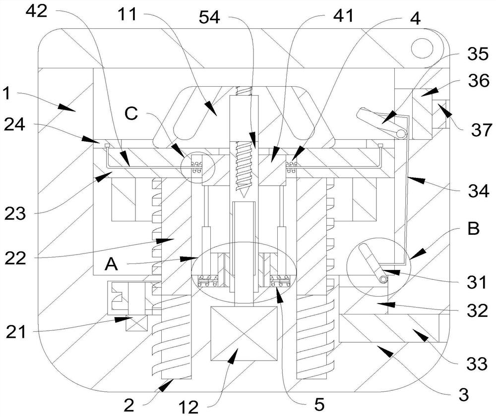
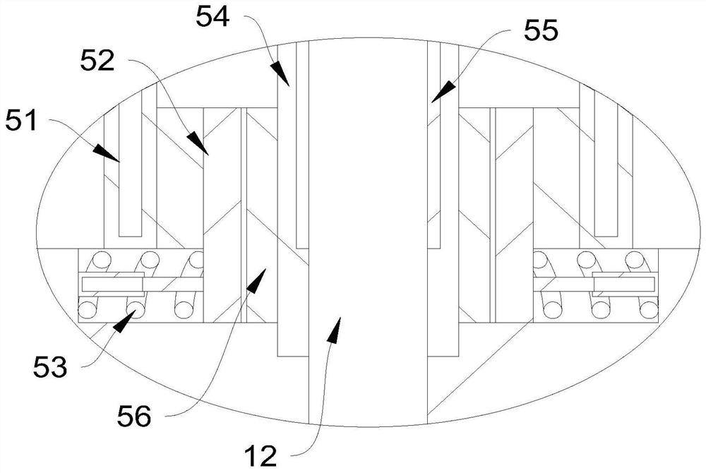
[0027] see Figure 1-8 An intelligent centrifuge for biological experiments, which includes a centrifuge body 1, an experimental rotor 11 for placing experimental test tubes, a lifting and limiting main part 2, a cleaning main part 4 and an indexing and placing main part 5, a centrifuge body 1 There is a centrifugal cavity inside, a centrifugal motor 12 is arranged in the center side of the bottom of the centrifugal cavity, the main part 5 for indexing is placed at the bottom of the centrifugal cavity, and the experimental rotor 11 is placed on the top of the main part 5 for indexing, and the main part 5 for indexing is placed. The member 5 includes a clamping mechanism and an indexing limiting mechanism, the clamping mechanism and the indexing limiting mechanism are both located at the periphery of the centrifugal main shaft of the centrifugal motor 12, and the clamping mechanism is arranged at the peripheral position of the indexing limiting mechanism, and the indexing limiti...


PUM


Abstract

The invention discloses an intelligent centrifuge for biological experiments, which belongs to the field of centrifuges. An intelligent centrifuge for biological experiments, comprising a centrifuge body, an experimental rotor for placing experimental test tubes, a lifting and limiting main part, a cleaning main part and an indexing and placing main part, the centrifuge body is provided with a centrifugal cavity, A centrifugal motor is arranged in the center side position of the bottom of the centrifugal chamber, the main part of the indexing and placing is arranged at the bottom of the centrifugal chamber, and the experimental rotor is placed on the top of the main part of the indexing and placing, and the main part of the indexing and placing includes a clamping mechanism and The indexing limiting mechanism, the clamping mechanism and the indexing limiting mechanism are all located on the periphery of the centrifugal main shaft of the centrifugal motor. By pushing the rotor in a supportive manner, it is convenient for the rotor to be pushed out. When pushing out, the surface on which the rotor is placed is wiped, and at the same time Filter out the moisture, condensed water and corrosive gas in the centrifuge.

Description

technical field [0001] The invention relates to the field of centrifuges, and more particularly, to an intelligent centrifuge for biological experiments. Background technique [0002] A centrifuge is a machine that uses centrifugal force to accelerate the separation of different materials that need to be separated. In biological experiments, in order to ensure the biological activity of the experimental substances, it is necessary to use a centrifuge with a freezing function to avoid the changes in the form of the biological substances at high temperatures, which will affect the accuracy of the experiment. When placing test tubes to be tested in the rotor, because the test tubes to be placed are symmetrical, it is inconvenient for the experimenter to place them in the same position during the placement process. [0003] In the case of improper use of the refrigerated centrifuge, condensed water or accidentally spilled liquid may infiltrate between the place where the rotor ...

Claims


Application Information

Patent Timeline
Patent Type & Authority Patents(China)
IPC IPC(8): B04B5/04B04B15/06B04B7/00
CPCB04B5/0414B04B15/06B04B7/00
Inventor 王玉轩宋玉伟王玉泽陈玲玲苏克锋
Owner NANYANG NORMAL UNIV
Why Eureka
Try Eureka