Inertial pre-dedusting flue gas distributor of deduster

A technology of distributing device and dust collector, applied in the direction of combination device, separation method, dispersed particle separation, etc., can solve the problems of filter bag damage, reduce the dust removal efficiency of the bag filter, reduce the service life of the filter bag, etc. The effect of reducing the probability of breakage and prolonging the service life

Inactive Publication Date: 2014-09-24
JIANGSU NEW ENVIRONMENTAL CORP
View PDF4 Cites 6 Cited by
  • Summary
  • Abstract
  • Description
  • Claims
  • Application Information

AI Technical Summary

Problems solved by technology

[0002] The structure of the bag filter includes: a dust collector box, a smoke inlet pipe and a smoke outlet pipe. The dust collector box is divided into an upper clean room and a lower smoke room by a flower plate. The filter bag connected to the air chamber has an air inlet in the lower flue gas chamber of the dust collector box, and an air outlet in the upper clean air chamber; the smoke inlet pipe is connected with the air inlet of the lower flue gas chamber of the dust collector box The air outlet of the upper clean room of the dust collector box is connected with the smoke outlet pipe; the disadvantage of this bag filter is: because the dusty flue gas contains a large amount of large particles of dust (dust particle size greater than 50μm), When the dust-containing flue gas is discharged into the lower flue gas chamber through the smoke inlet pipe at a relatively high flue gas flow rate, since there is no flue gas pre-dust removal distribution device in the lower flue gas chamber, the dust-laden flue gas entering the lower flue gas chamber will be directly discharged into the lower flue gas chamber. The filter bag is impacted, and at the same time, the large particles of dust in the dusty flue gas will directly wash the filter bag, so that the filter bag is easily damaged, which not only greatly reduces the service life of the filter bag, but also reduces the filter bag. Dust removal efficiency of dust collector

Method used


Image

  • Inertial pre-dedusting flue gas distributor of deduster
  • Inertial pre-dedusting flue gas distributor of deduster
  • Inertial pre-dedusting flue gas distributor of deduster

Examples


Embodiment Construction

[0012] The present invention will be further described below in conjunction with the accompanying drawings and specific embodiments.

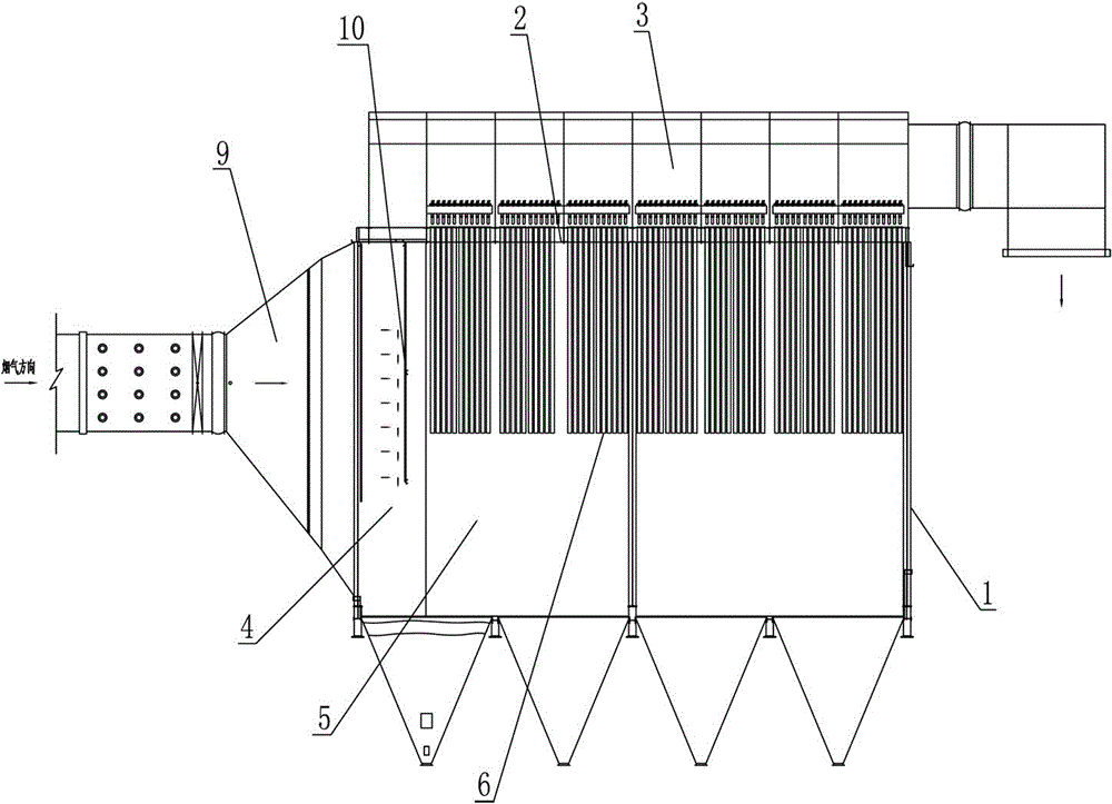
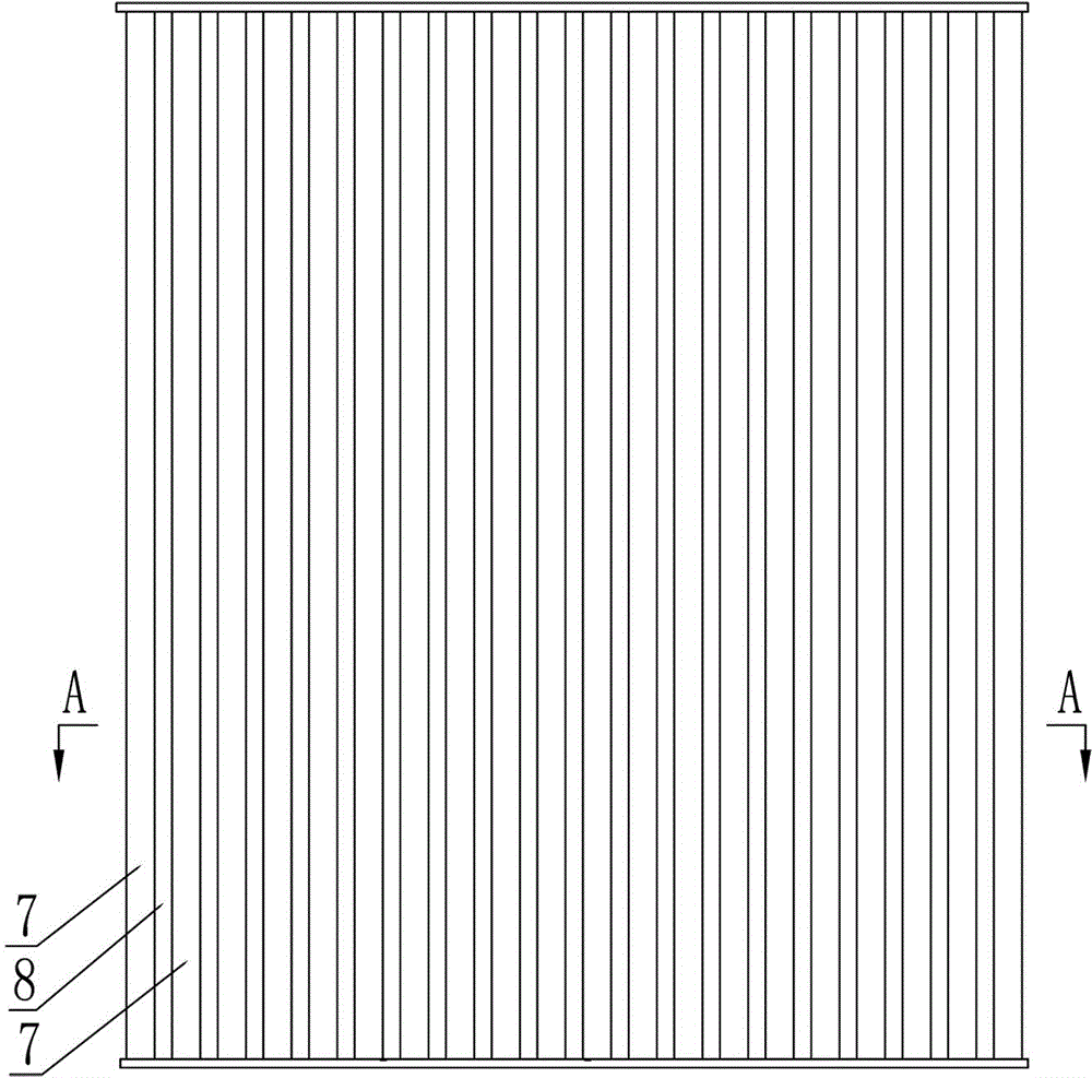
[0013] Such as figure 1 , figure 2 , image 3 , Figure 4 , Figure 5 As shown, the inertial pre-dust removal flue gas distribution device of the dust collector includes: the dust collector box 1, the dust collector box 1 is divided into an upper clean gas chamber 3 and a lower flue gas chamber by a flower plate 2, and the lower flue gas chamber It is composed of the connected pre-cleaning room 4 and the bag-cleaning room 5. On the flower plate of the bag-cleaning room 5, there are several filter bags 6 connected with the upper air-cleaning room 3. The pre-dusting room of the dust collector box 1 4 is provided with an air inlet, and the upper clean air chamber 3 is provided with an air outlet; in the pre-dust removal chamber 4, a number of flue gas pre-dust removal distribution mechanisms 10 are sequentially arranged at intervals along the...


PUM

PropertyMeasurementUnit
particle diameteraaaaaaaaaa

Abstract

The invention discloses an inertial pre-dedusting flue gas distributor of a deduster. The flue gas distributor comprises a dust collector box. The dust collector box is divided by a card into an upper clean gas chamber and a lower flue gas chamber; the lower flue gas chamber comprises a pre-dedusting chamber and a cloth bag dedust chamber, which are communicated; the card in the cloth bag dedust chamber is hanged with a filter bag; the pre-dedusting chamber of the dust collector box is provided with an air inlet, and an air outlet is arranged on the upper clean gas chamber; the pre-dedusting chamber along the flue gas inlet direction is sequentially equipped with a plurality of flue gas pre-dedusting distribution mechanisms; the flue gas pre-dedusting distribution mechanism comprises a plurality of front groove-shaped baffles and rear groove baffles, which are vertically arranged on the pre-dedusting chamber; the notches of all the front groove-shaped baffles are arranged in the flue gas inlet direction; all notches of the rear groove-shaped baffles are arranged all against the flue gas inlet direction; every two adjacent front groove-shaped baffles buckle with one rear groove-shaped baffle; and a gap is left between each rear groove-shaped baffle and the buckled front groove-shaped baffle. The filter bag provided by the invention has the advantage of long service life.

Description

technical field [0001] The invention relates to a dust collector, in particular to a dust collector inertial pre-dust removal flue gas distribution device in the dust collector. Background technique [0002] The structure of the bag filter includes: a dust collector box, a smoke inlet pipe and a smoke outlet pipe. The dust collector box is divided into an upper clean room and a lower smoke room by a flower plate. The filter bag connected to the air chamber has an air inlet in the lower flue gas chamber of the dust collector box, and an air outlet in the upper clean air chamber; the smoke inlet pipe is connected with the air inlet of the lower flue gas chamber of the dust collector box The air outlet of the upper clean room of the dust collector box is connected with the smoke outlet pipe; the disadvantage of this bag filter is: because the dusty flue gas contains a large amount of large particles of dust (dust particle size greater than 50μm), When the dust-containing flue ...

Claims


Application Information

Patent Timeline
Patent Type & Authority Applications(China)
IPC IPC(8): B01D45/08B01D50/00
Inventor 顾建清
Owner JIANGSU NEW ENVIRONMENTAL CORP
Why Eureka
Try Eureka