Eureka AIR delivers breakthrough ideas for toughest innovation challenges, trusted by R&D personnel around the world.

Conveying device for electric power copper pipe flaring machine

A technology of flaring machine and copper pipe, which is applied in the field of pipe material processing, can solve the problems of many fault sources, high cost, long length, etc., and achieve the effect of improving processing efficiency

Inactive Publication Date: 2014-09-24
STATE GRID CORP OF CHINA +1
View PDF8 Cites 2 Cited by
  • Summary
  • Abstract
  • Description
  • Claims
  • Application Information

AI Technical Summary

Problems solved by technology

[0002] Existing tube flaring machines are generally longer in length, larger in space, higher in cost and more in fault sources, and their structure needs to be improved urgently

Method used


Image

  • Conveying device for electric power copper pipe flaring machine
  • Conveying device for electric power copper pipe flaring machine
  • Conveying device for electric power copper pipe flaring machine

Examples


Embodiment 1)

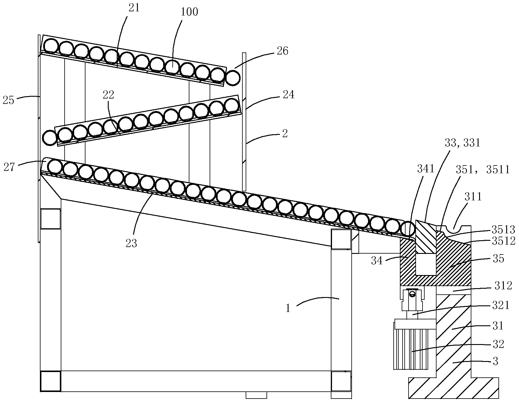
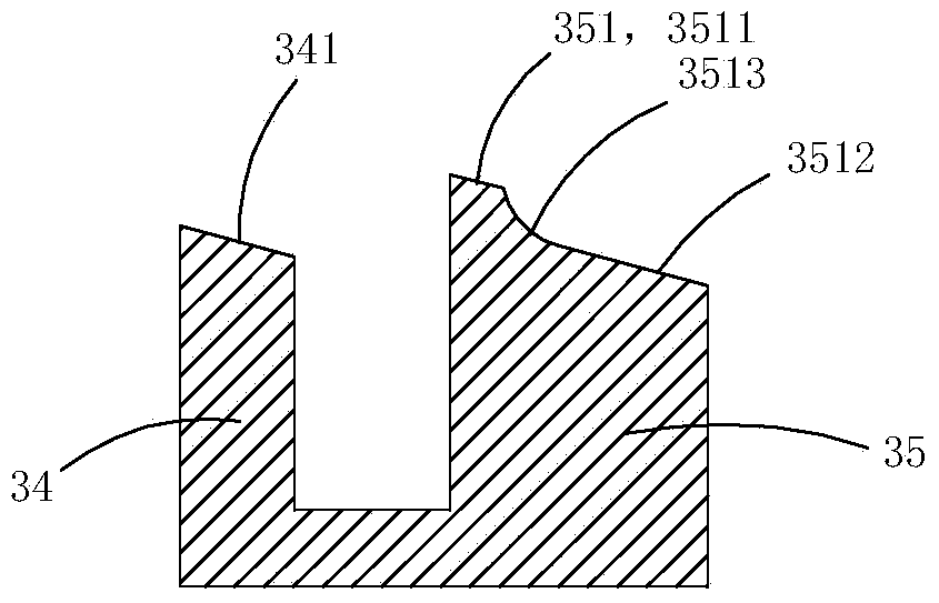
[0014] figure 1 and figure 2 A specific embodiment of the invention is shown in which, figure 1 It is a structural schematic diagram of the present invention; figure 2 for figure 1 A schematic diagram of the structure of the feeding jack and the discharging jack in the ejecting device shown.

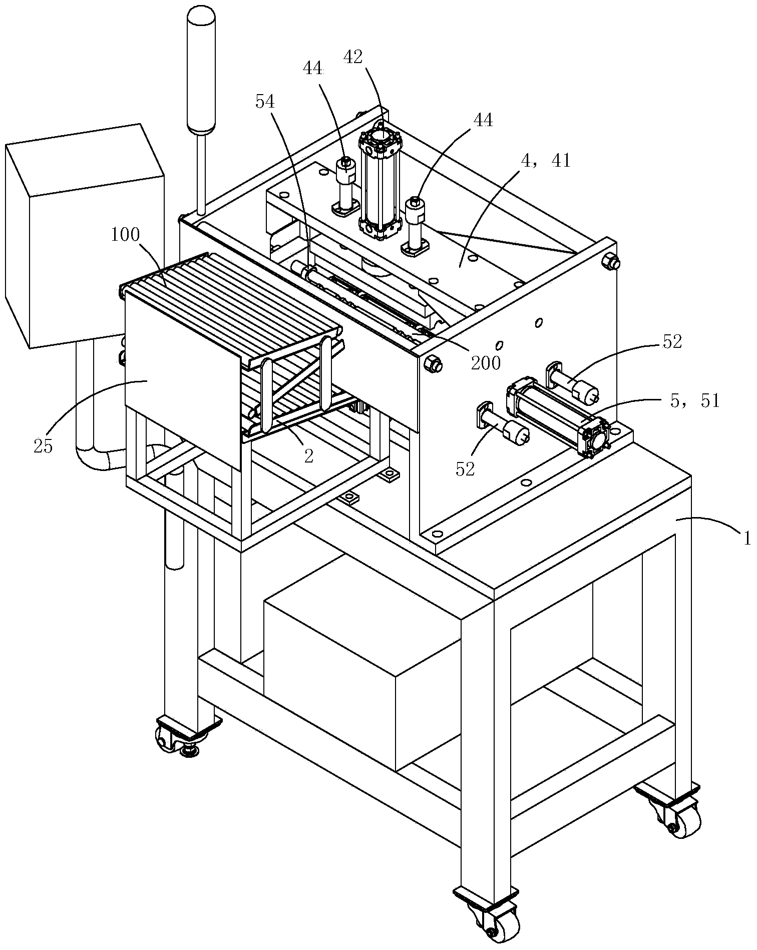
[0015] Present embodiment is the feeding device that is used for electric copper pipe belling machine, see Figure 1 to Figure 2 As shown, it includes a support 1, a feeding mechanism 2 and a feeding mechanism 3.

[0016] The feeding mechanism comprises the first feed plate 21, the second feed plate 22, the third feed plate 23, the front feed plate 24 and the rear feed plate 25, the first feed plate, the second feed plate, the second feed plate The cross-sectional shape of the three feeding boards is U-shaped; the first feeding board, the second feeding board, and the third feeding board are all inclined at an angle with the horizontal plane, and combined to form an inclined Z-sha...


PUM


Abstract

The invention discloses a conveying device for an electric power copper pipe flaring machine. The conveying device comprises a supporting piece, an ejection cylinder, a separator, a feeding ejection column and a discharge ejection column, wherein the top wall of the supporting piece is provided with a semicircular supporting groove matched with a pipe, the ejection cylinder is arranged on the supporting piece, the separator is fixedly arranged on the supporting piece and adjacent to the front end of a conveying mechanism, the feeding ejection column is used for ejecting up a pipe adjacent to the separator in the conveying mechanism, and the discharge ejection column is used for ejecting up the pipe in the semicircular supporting groove of the supporting piece; the supporting piece is fixedly arranged on a support; the separator is arranged between the supporting piece and the conveying mechanism; the feeding ejection column and the discharge ejection column are fixedly arranged on an ejection cylinder piston; the ejection cylinder piston synchronously drives the feeding ejection column and the discharge ejection column to conduct upward ejection. By means of the conveying device, pipes to be flared can be synchronously sent to preset machining positions, and flared pipes can be moved out of the machining positions, so that machining efficiency is effectively improved.

Description

technical field [0001] The invention belongs to the technical field of tube material processing, and in particular relates to a material delivery device for an electric copper tube belling machine. Background technique [0002] Existing tube flaring machines are generally longer in length, larger in space, higher in cost and more in fault sources, and their structure needs to be improved urgently. Contents of the invention [0003] The object of the present invention is to provide a material delivery device for an electric copper tube belling machine that can simultaneously feed in and remove material tubes, thereby improving processing efficiency. [0004] The technical solution for realizing the object of the present invention is: a material delivery device for an electric copper tube belling machine, comprising a support member whose top wall is provided with a semicircular support groove adapted to the material pipe, and a support member arranged on the support member....

Claims


Application Information

Patent Timeline
Patent Type & Authority Applications(China)
IPC IPC(8): B21D41/02B21D43/16B21D45/02
CPCB21D41/02B21D43/003B21D43/006B21D43/16B21D45/02
Inventor 申俊
Owner STATE GRID CORP OF CHINA
Why Eureka
Eureka Blog
Learn More