Scroll Compressor

A scroll compressor and scroll technology, applied in the field of compressors, can solve the problems of complex structure, vibration and noise of the upper back pressure scroll compressor.

Active Publication Date: 2014-09-24
LG ELECTRONICS INC
View PDF9 Cites 7 Cited by
  • Summary
  • Abstract
  • Description
  • Claims
  • Application Information

AI Technical Summary

Problems solved by technology

This can cause the first scroll to tilt, causing vibration and noise
In addition, O-rings that prevent compressed refrigerant from leaking out wear out quickly
The structure of the upper back pressure type scroll compressor is complex

Method used


Image

  • Scroll Compressor
  • Scroll Compressor
  • Scroll Compressor

Examples


Embodiment Construction

[0045] Referring to the accompanying drawings, a detailed description will now be given of the embodiments. Where possible, like reference numerals are used to designate like elements, and repeated descriptions are omitted.

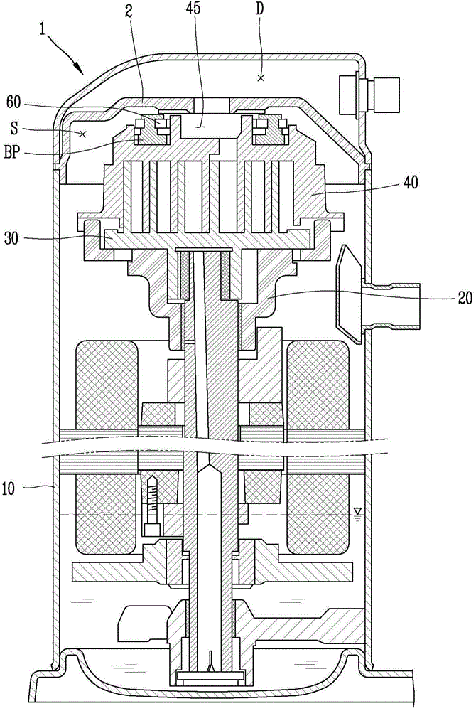
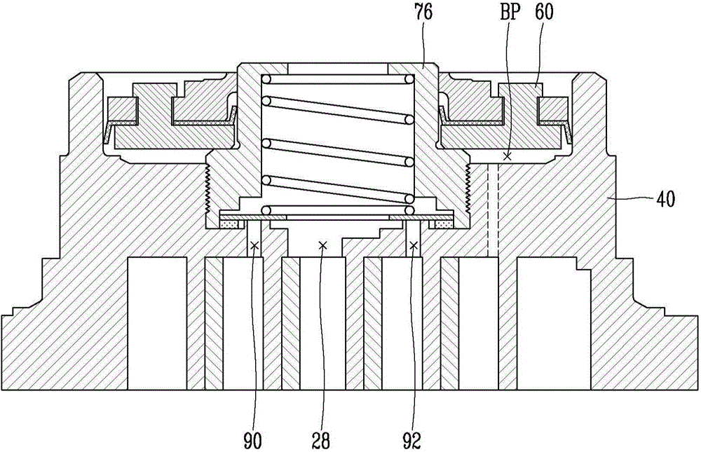
[0046] refer to figure 2 , overloading in upper back pressure type scroll compressors is prevented by using the scroll compressor bypass holes and related components to mitigate pressure imbalances. However, since the hub member 76 can be arranged in the back pressure chamber BP, the positions of the bypass holes 90 , 92 cannot be arbitrarily set. That is, in order to obtain a sufficient back pressure with the back pressure chamber BP, the back pressure chamber BP should be formed in a predetermined size at a predetermined position. This can limit the size of the hub member 76 . Accordingly, the location of the bypass holes 90 , 92 may be limited to the area below the hub member 76 .

[0047] Furthermore, the floating plate 60 should seal the back pr...


PUM


Abstract

A scroll compressor having a bypass is provided. The scroll compressor may include a casing, a discharge cover, a main frame, a first scroll supported by the main frame, and a second scroll that forms a suction chamber, an intermediate pressure chamber, and a discharge chamber together with the first scroll. The second scroll may include a bypass hole that communicates with the intermediate pressure chamber. The scroll compressor may also include a back pressure chamber assembly coupled to an upper portion of the second scroll by a fastening device and a bypass valve to open and close the bypass hole. The back pressure chamber assembly may include a discharge path by which the discharge chamber and the discharge space may communicate with each other and a bypass valve to open and close the bypass hole.

Description

technical field [0001] A compressor is disclosed herein, and more particularly, a scroll compressor with a bypass. Background technique [0002] Scroll compressors are known. However, such compressors have various disadvantages. [0003] A scroll compressor is a compressor that utilizes a first or orbiting scroll with a spiral wrap and a second or fixed scroll with a spiral wrap, the first scroll performing relative to the second scroll orbiting motion. When the first scroll and the second scroll are engaged with each other in operation, as the first scroll performs an orbiting motion, the pressure chamber formed between the first scroll and the second scroll capacity can be reduced. Accordingly, the pressure of the fluid in the pressure chamber may be increased, and the fluid is discharged from the discharge port formed at the central portion of the second scroll. [0004] When the first scroll performs an orbiting motion, the scroll compressor may continuously perform...

Claims


Application Information

Patent Timeline
Patent Type & Authority Applications(China)
IPC IPC(8): F04C18/02F04C29/00
CPCF04C23/008F04C18/0215F04C18/04F04C28/26F04C18/023F04C27/005F04C18/0261
Inventor 金洙喆陈弘均朴基元尹周焕
Owner LG ELECTRONICS INC
Why Eureka
Try Eureka