
Pneumatic self-locking switch valve

A technology of self-locking switch and spool, which is applied in the direction of control valves, air release valves, brakes, valve details, etc., which can solve the problem that the two-position three-way air-controlled hydraulic reversing valve cannot be reset and cannot realize effective parking brake, The on-off valve cannot be cut off by itself, so as to achieve the effect of strengthening practical value, improving safety and reliability, and working stably

Active Publication Date: 2016-08-03
TAIYUAN INST OF CHINA COAL TECH & ENG GROUP +1
View PDF6 Cites 0 Cited by
  • Summary
  • Abstract
  • Description
  • Claims
  • Application Information

AI Technical Summary

Problems solved by technology

The ordinary pneumatic switch valve realizes the manual control of the parking brake control air circuit, but the following problems occur during the use of the vehicle: (1) After the vehicle is normally turned off, the switch valve cannot be cut off by itself. Manually closed, resulting in two-two three-way air-controlled hydraulic reversing valve cannot be reset or reset incompletely, and effective parking brake cannot be realized, posing a major safety hazard
(2) The vehicle is turned off due to lack of water, high oil temperature, etc. due to electrical protection or insufficient air pressure. If the on-off valve is not closed, the parking brake will not be released artificially after the problem is solved and the vehicle returns to normal, which may cause an accident

Method used


Image

  • Pneumatic self-locking switch valve
  • Pneumatic self-locking switch valve
  • Pneumatic self-locking switch valve

Examples


Embodiment Construction

[0019] The specific embodiment of the present invention will be further described in conjunction with the accompanying drawings.

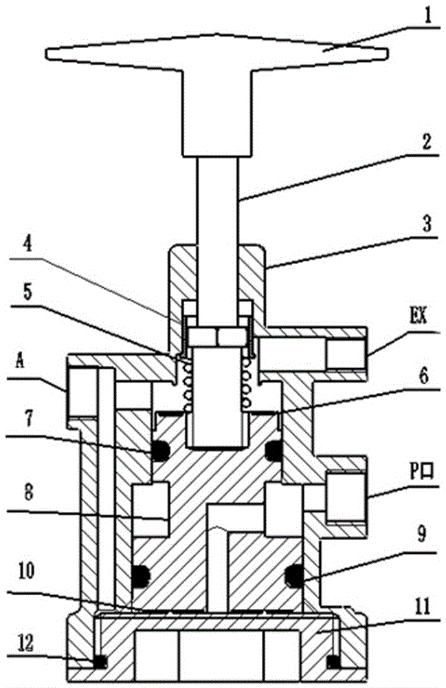
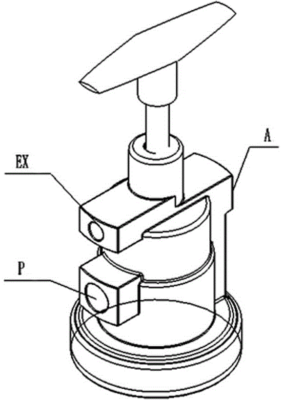
[0020] Such as figure 1 As shown, the pneumatic automatic shut-off valve is mainly composed of handle, valve stem, valve casing, valve core, end cover, sleeve, spring and sealing ring and other components. Valve pressure port P, work port A, exhaust port Ex (such as figure 2 shown) are respectively connected with the gas source, the controlled element and the outside atmosphere.

[0021] The valve core 8 and the valve stem 2 are both circumferentially set in the valve housing 3, and the end cover 11 is connected to the valve housing 3 through threads;

[0022] Three cavities can be formed between the valve core 8, the valve housing 3 and the end cover 11, that is, the spring cavity on the valve stem 2 side of the valve core 8, the middle cavity formed by the middle groove of the valve core 8, and the valve core 8 close to the end cover. Side 11...


PUM


Abstract

The invention belongs to the technical field of pneumatic switch valves, in particular to a pneumatic self-locking switch valve, and solves the problems of the conventional pneumatic switch valves. A valve core and a valve rod of the switch valve are all sleeved with a valve casing in the circumferential direction; a reset spring sleeves the valve rod between the valve casing and the top end of the valve core; a pressure port, a working port and an air outlet, which are respectively connected with an air source, a controlled element and the outside atmosphere, are formed in the valve casing; three cavities are formed among the valve core, the valve casing and an end cover; a spring cavity is always communicated with the air outlet; a middle cavity is always communicated with the pressure port; a communication hole which penetrates through the center of the end face at the bottom of the valve core from the middle cavity is formed in the valve core; the working port is respectively communicated with the spring cavity and the valve end cover cavity through communication holes; the three cavities are segregated by the matching of the valve core and the valve casing. The pneumatic self-locking switch valve has the advantages of good leak tightness, high working stability and long service life, and can realize that the switch valve can be switched on and off freely through manual operation when air pressure in an air channel is normal; the switch valve can be automatically cut off when the pressure in the air channel is insufficient; the switch valve can only be manually unlocked after the air pressure recovers.

Description

technical field [0001] The invention belongs to the technical field of pneumatic switch valves, in particular to a pneumatic self-locking switch valve. Background technique [0002] With the extensive use of trackless rubber-tyred vehicles in coal mines, the requirements for their safety and reliability are getting higher and higher. The pneumatic control system and its components are applied to the starting, protection and parking brake systems of mine trackless rubber-tyred vehicles due to their safety, portability, economy and reliability. The hydraulic system of the mine trackless rubber-tyred vehicle is to unload and fill the piston rod cavity of the brake through the two-position three-way air-controlled hydraulic reversing valve to realize the parking brake or release of the vehicle. In order to ensure that the vehicle can realize the parking brake (or switch between the driving mode and the hydraulic working structure operation mode) when the hydraulic working mecha...

Claims


Application Information

Patent Timeline
Patent Type & Authority Patents(China)
IPC IPC(8): F16K17/168B60T15/36
CPCB60T15/36F16K17/0473F16K17/0486F16K27/041
Inventor 柳玉龙樊瑞龙马艳卫安四元陈利东刘德宁周旭
Owner TAIYUAN INST OF CHINA COAL TECH & ENG GROUP
Learn More