
A static stiffness testing device and method for joints of rolling linear guide rail pairs

A technology of linear guide rail pair and testing device, which is applied in the testing of machine/structural parts, measuring device, testing of mechanical parts, etc., can solve the problems of difficulty in loading the stiffness test, difficulty in testing the stiffness of the joint part of the guide rail pair, etc., and achieve convenient load The effect of measuring and controlling

Active Publication Date: 2016-06-01
XIAN UNIV OF TECH
View PDF7 Cites 0 Cited by
  • Summary
  • Abstract
  • Description
  • Claims
  • Application Information

AI Technical Summary

Problems solved by technology

[0004] The purpose of the present invention is to provide a static stiffness test device for the joint of rolling linear guide rails, which solves the problem that it is difficult to test the stiffness of each stiffness under the existing technical conditions, and it is more difficult to complete the stiffness test of the joints of guide rails with different specifications and sizes.

Method used


Image

  • A static stiffness testing device and method for joints of rolling linear guide rail pairs
  • A static stiffness testing device and method for joints of rolling linear guide rail pairs
  • A static stiffness testing device and method for joints of rolling linear guide rail pairs

Examples


Embodiment Construction

[0040] The present invention will be described in further detail below in conjunction with the accompanying drawings and specific embodiments.

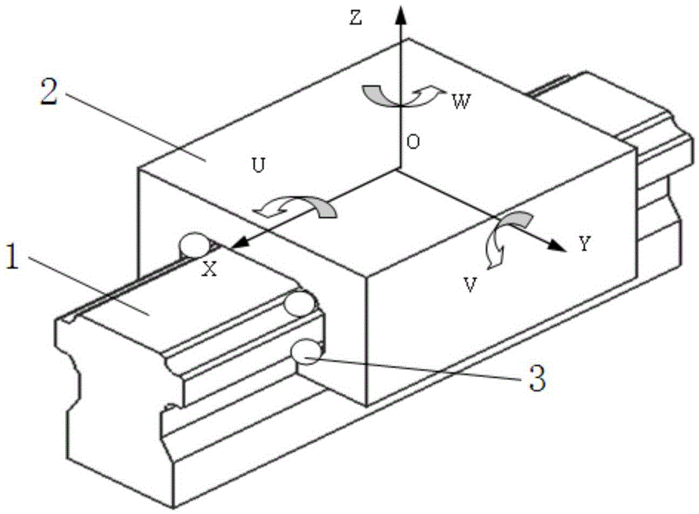
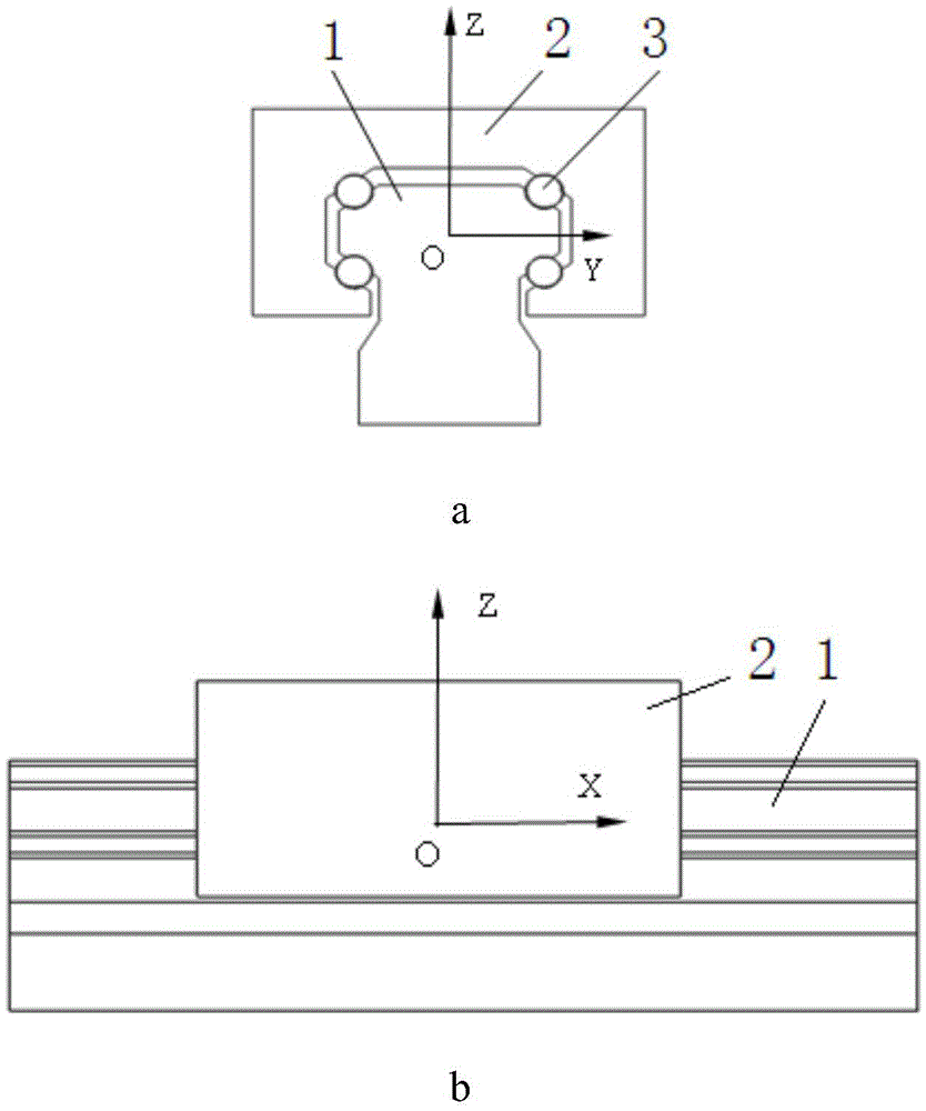
[0041] figure 1 Define the schematic diagram for the guide rail secondary coordinate system, figure 2 It is a projected view of the guide rail sub-coordinate system. There are multiple groups of rolling bodies 3 arranged between the guide rail bar 1 and the guide rail block 2. The coordinate origin O is defined in the symmetrical position plane of the upper and lower four rows of rolling bodies 3, that is, the X direction and the Y direction. , the intersection of the symmetrical planes in the Z direction, the guide rail auxiliary coordinate system XYZ-O is located at the symmetrical position of the four rows of rolling elements 3 of the guide rail block 2, and the Z axis is vertical to the top surface of the guide rail block 2, which is called the normal direction and is located at its symmetrical position; the X axis Along the mov...


PUM


Abstract

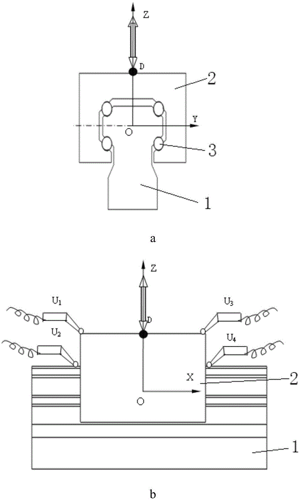
The invention discloses a static stiffness testing device for the joint part of a rolling linear guide rail. Three positioning holes A, B and C are arranged on the bridge type box body; Stiffness test loading; fix the tensile load loading mechanism in the positioning hole A, and perform normal tensile stiffness test loading; fix the pressure load loading mechanism in the positioning hole B, and perform lateral stiffness test loading; fix the torque loading mechanism in the positioning In hole A, carry out angular stiffness test loading around the Z axis; fix the torque loading mechanism in positioning hole B, and carry out angular stiffness test loading around the Y axis; fix the torque loading mechanism in positioning hole D on the front panel of the bridge box , to carry out angular stiffness test loading around the X axis. The invention also discloses a method for testing the static stiffness of the joint part of the rolling linear guide rail pair. The device and method of the present invention adopt a modular structure design, which can meet the requirements of stiffness testing of guide rails of different specifications.

Description

technical field [0001] The invention belongs to the technical field of mechanical equipment manufacturing, and relates to a device for testing the static stiffness of a joint of a rolling linear guide rail, and also relates to a method for testing the static stiffness of a joint of a rolling linear guide rail. Background technique [0002] Rolling linear guides are widely used in CNC machine tools, robots and other CNC equipment, and are the main functional components for low-friction feed of moving parts in CNC equipment. The rolling linear guideway pair is to place rolling elements (balls, rollers) between the guideway block and the guideway bar (supporting guideway), so as to realize the extremely low rolling friction transmission between the guideway block and the guideway bar. The inter-part (including the rolling elements) constitutes the junction of the rolling linear guide pair. The stiffness of the joint of the rolling linear guide pair (that is, the stiffness of t...

Claims


Application Information

Patent Timeline
Patent Type & Authority Patents(China)
IPC IPC(8): G01M13/00G01N3/00
Inventor 张广鹏王佳丽袁冲冯驰黄玉美
Owner XIAN UNIV OF TECH
Learn More