
Calculation method for large-area region cloud-to-ground lightning density based on improved grid method

It is a technique for ground flash density and large area, which is applied in calculation, special data processing applications, instruments, etc. It can solve the problems of reducing the amount of calculation and inaccurate calculation results of ground flash density, and achieves the effect of accurate calculation results

Inactive Publication Date: 2014-09-24
TSINGHUA UNIV +1
View PDF1 Cites 9 Cited by
  • Summary
  • Abstract
  • Description
  • Claims
  • Application Information

AI Technical Summary

Problems solved by technology

Although this method adopts the radian division method of latitude and longitude with different precision when dividing the grid, it considers the grid cell area of ​​each precision to be equal, ignoring the influence of the latitude of the grid cell on the grid area, because the latitude The circumference of the circle gradually becomes smaller as the latitude increases, and the area of ​​the grid unit also decreases as the latitude of the grid increases. Because this method assumes that the area of ​​all grid units is equal when calculating the flash density of the grid unit, This can reduce the amount of calculation when the difference in latitude between the north and the south of the selected area is small, but in a large area with a large difference in latitude between the north and the south (the difference between the north and the south latitude is greater than or equal to 10°), it will introduce a large error, resulting in inaccurate calculation results of the ground flash density

Method used


Image

  • Calculation method for large-area region cloud-to-ground lightning density based on improved grid method
  • Calculation method for large-area region cloud-to-ground lightning density based on improved grid method
  • Calculation method for large-area region cloud-to-ground lightning density based on improved grid method

Examples


Embodiment

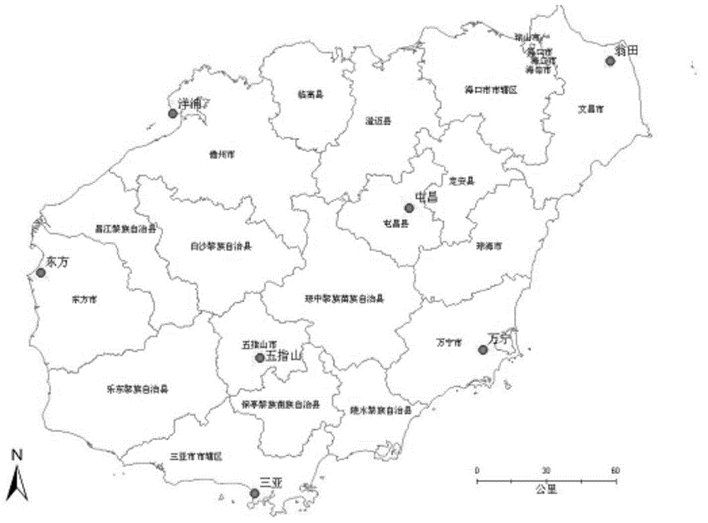
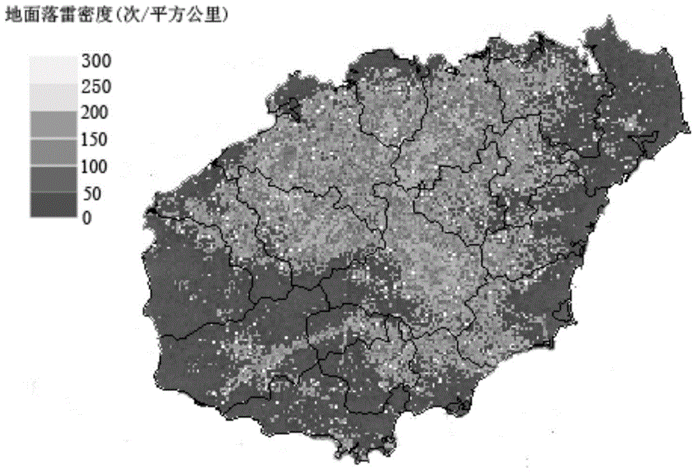
[0033] The specific embodiment of the present invention will now be described in conjunction with the statistical data of the Hainan Island lightning location system. figure 2 It is the distribution map of the detection stations of the lightning location system in Hainan Island. There are 7 detection stations in total. The present invention adopts computer to enter the historical data of the lightning location system of Hainan Island in 2010, and uses the computer to process the data. The data sample table is shown in Table 1; Select 0.01°×0.01°, and calculate the area of ​​each grid cell N according to formula (1) g ; Then, statistically calculate the number of ground lightning strikes N of each grid cell in 2010; then, substitute the result into formula (2) to obtain the flash density of each grid cell; finally, calculate the flash density of each grid in the displayed on the digital map, such as image 3 As shown, the darker the color in the figure, the smaller the densi...


PUM


Abstract

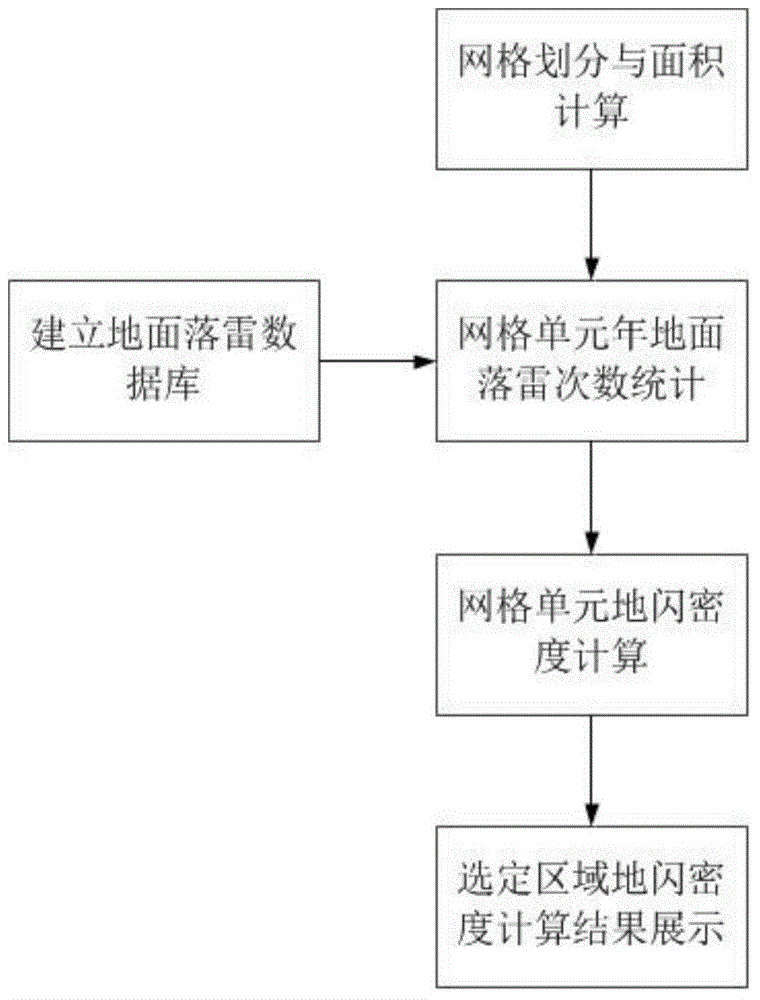
The invention relates to a calculation method for large-area region cloud-to-ground lightning density based on an improved grid method. The calculation method belongs to the technical field of power line design. The calculation method comprises the steps that a ground lightning database is created, and the database contains ground lightning time and geographical position information; the longitude range and latitude range of a selected region are divided into different grid cells according to selected accuracy, the left and right sides of the grid cell coincide with the longitude line, and the upper and lower sides of the grid cell coincide with the altitude line, the division accuracy is set to be p, the altitude of one side, close to the equator, of the upper and lower sides of the grid cell is lat, and the area of each grid cell is calculated; the annual ground lightning times of each grid cell is calculated according to the data statistics of the ground lightning database; the cloud-to-ground density of each grid cell is calculated according to the divided grid areas; the calculation result is displayed in a digital map. The calculation method can calculate the cloud-to-ground lightning density of regions with large latitude difference more accurately and provide an effective reference frame for the selection of lightning protection level in power line design and reconstruction.

Description

technical field [0001] The invention belongs to the technical field of power circuit design, and in particular relates to an improved method for calculating ground flash density by using a grid method for a large area. Background technique [0002] The ground flash density is the number of cloud-to-ground lightning strikes per square kilometer per year, which characterizes the frequency of lightning discharges from thunder clouds to the ground, and is one of the basic parameters for evaluating the lightning resistance level of transmission lines. At present, in the design and transformation of power lines, the annual average lightning days, ground lightning strikes, ground flash density and other information collected by conventional ground meteorological observation stations are still used as the basic data for the assessment of the lightning resistance level of transmission lines. According to the relevant regulations: if a weather station manually records a sound of light...

Claims


Application Information

Patent Timeline
IPC IPC(8): G06F19/00
Inventor 高文胜张博文周瑞旭符祥干陈钦柱黄松梁亚峰
Owner TSINGHUA UNIV
Learn More