
Tetrahedral mesh generation method and device for three-dimensional solid model

A tetrahedral mesh and solid model technology, applied in 3D modeling, image data processing, instruments, etc., can solve problems such as dynamic recovery, limited geometric boundary features, and inability to dynamically restore and correct geometric boundary features of the model. To achieve the effect of efficient generation

Active Publication Date: 2014-09-24
TSINGHUA UNIV
View PDF6 Cites 34 Cited by
  • Summary
  • Abstract
  • Description
  • Claims
  • Application Information

AI Technical Summary

Problems solved by technology

[0005] The input of the traditional distributed and parallel tetrahedral mesh generation algorithm is mainly the surface sampling vertex set or the face mesh set of the model, and on this basis, parallel volume mesh generation is performed, so the geometric boundary of the volume mesh is finally generated The feature is limited by the input vertex set or face mesh set, and the geometric boundary features of the model cannot be dynamically restored and corrected in the parallel process; the traditional tetrahedral mesh generation algorithm cannot dynamically restore the geometric features of the model in the parallel process, so During the serial preprocessing stage, a very dense sample of the model surface must usually be generated to maintain a certain mesh accuracy, so the initial mesh generation takes a lot of time
Subsequently, parallel volume mesh generation is performed on this basis, so the geometric boundary characteristics of the final generated volume mesh are limited by the input vertex set or surface mesh set, and the geometric boundary characteristics of the model cannot be dynamically restored and corrected in the parallel process. As the grid size continues to increase, the accuracy of the grid cannot be improved

Method used


Image

  • Tetrahedral mesh generation method and device for three-dimensional solid model
  • Tetrahedral mesh generation method and device for three-dimensional solid model
  • Tetrahedral mesh generation method and device for three-dimensional solid model

Examples


Embodiment Construction

[0024] In order to enable those skilled in the art to better understand the present invention, the present invention will be further described in detail below in conjunction with the accompanying drawings and specific embodiments.

[0025] Before describing the embodiments of the present invention in detail, in order to facilitate those skilled in the art to understand and grasp the present invention, the main idea of ​​the present invention is described below.

[0026] The main input of the traditional technology is the surface sampling vertex set or the face mesh set, which loses the 3D model information, so that the geometric boundary characteristics of the final volume mesh are limited by the input vertex set or the face mesh set, and cannot be dynamically processed in a parallel process. Restores the geometric boundary features of the model. In view of this, the inventor thought of performing rough sampling in the model boundary sampling stage, and bringing in 3D model in...


PUM


Abstract

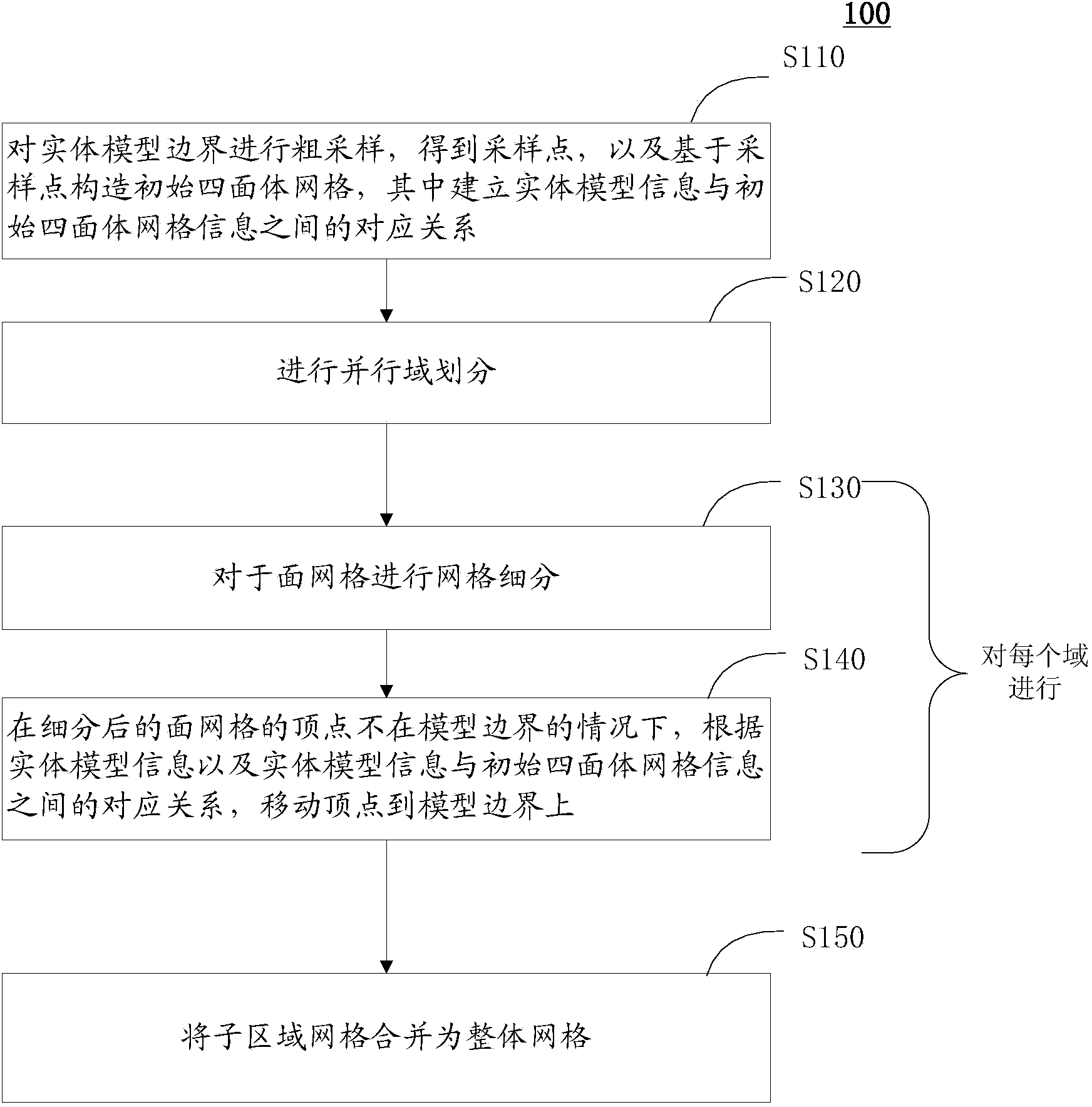
The invention provides a tetrahedral mesh generation method and device for a three-dimensional solid model. The method comprises the steps that coarse sampling is carried out on the solid model boundary, an initial tetrahedral mesh is built based on sampling points, and the corresponding relation between solid model information and initial tetrahedral mesh information is built; parallel domain partition is carried out; mesh subdivision and mesh optimization are carried out on parted areas in parallel, wherein the mesh optimization is used for keeping the model boundary according to the solid model information; sub-area meshes are combined into a whole mesh. According to the tetrahedral mesh generation method and device, coarse sampling is carried out in the model boundary sampling stage, and three-dimensional model information is brought in the tetrahedral mesh generation process, so that geometric boundary characteristics of the model is dynamically recovered in the parallel process, and model boundary sampling can be efficiently achieved; due to the fact that mesh subdivision and mesh optimization are carried out in the follow-up parallel process, the model boundary characteristics can be kept, and meanwhile the tetrahedral mesh is efficiently generated.

Description

technical field [0001] The present invention generally relates to finite element analysis and simulation of three-dimensional solids, and in particular to a method and device for generating tetrahedral meshes of three-dimensional solid models. Background technique [0002] Some 3D objects and related analyzes in the real world (such as simulation and force analysis of buildings) need to be simulated by using finite element technology. [0003] A Delaunay tetrahedral mesh is a three-dimensional mesh widely used in finite element techniques, which has four vertices and four triangular-shaped faces. [0004] In order to carry out more accurate simulation in the process of finite element calculation and simulation analysis, Delaunay tetrahedral grids with larger scale, higher quality and smaller granularity are often required. As the size of the grid continues to increase, the time required to generate the Delaunay tetrahedron grid also increases significantly. Therefore, how t...

Claims


Application Information

Patent Timeline
IPC IPC(8): G06T17/30
Inventor 陈莉陈翔
Owner TSINGHUA UNIV
Learn More