Steam collection unit and cooking device with same

A cooking device and collection unit technology, applied in cooking utensils, household utensils, kitchen utensils, etc., can solve the problems of reduced heating efficiency, achieve the effect of saving pressure, improving cooking efficiency, and not easy to lose

Inactive Publication Date: 2014-10-01
PHILIPS (JIAXING) HEALTH AND TECHNOLOGY CO LTD
7 Cites 15 Cited by

AI-Extracted Technical Summary

Problems solved by technology

When cooking, steam and food smell come out directly from the vent hole of the steam valve, the pressure inside the pot decreases, and the heating efficiency decreases
In addition, the smell of food will ...

Method used

Referring to Fig. 2, in order to prevent the problem that the water storage box b-6 is not installed in place during use, the positioning groove b-9 is particularly set under the water box, and the decorative surface cover b-7 of the water storage box is fixed on the lower bottom for positioning Slot b-9 cannot be removed by general users. The water storage box b-6 is normally taken up and down. Only when a certain amount of water is put into the water storage box and the magnetic float b-11 floats up to a specific position and touches the magnetic switch of the cooker body, the rice cooker can be started. In addition, the rice cooker of this embodiment can adopt the leak-proof detachable inner cover disclosed in Chinese patent CN201220620681.8, and the upper cover steam collection assembly includes the detachable inner cover b-3 and the steam conduit assembly ( b-1 and b-2 combination), the rice cooker cannot be covered. This avoids misoperation caused by the user forgetting to install accessories during operation, and eliminates potential unsafe factors in certain operations.
[0030] Referring to Fig. 2, on the detachable inner cover plate b-3...

Abstract

The invention discloses a steam collection unit on a cooking device. The steam collection unit comprises a steam guide pipe, an inner cover plate, a cooling water storage box, an outer shell cover and a steam collection box, the cooling water storage box is arranged at the front end of the outer shell cover and comprises a water storage box cover and a water storage box body which are hermetically assembled together, a hole is formed in the water storage box cover, the steam guide pipe is connected into the cooling water storage box through the hole, the steam collection box is arranged below the water storage box cover in the cooling water storage box and comprises a steam collection box upper cover and a steam collection box body which are hermetically assembled together, the upper end of the steam collection box is provided with a guide pipe which is hermetically connected with the steam guide pipe connected into the cooling water storage box in a sleeved manner, steam enters the steam guide pipe through small holes in the inner cover plate, flows into the steam collection box from the hole in the water storage box cover and is cooled by cold water in the cooling water storage box, the steam entering the steam collection box is gradually liquefied into water. In addition, the invention further discloses the cooking device with the steam collection unit.

Application Domain

Technology Topic

Image

  • Steam collection unit and cooking device with same
  • Steam collection unit and cooking device with same
  • Steam collection unit and cooking device with same

Examples

  • Experimental program(1)

Example Embodiment

[0025] The present invention will be further explained below in conjunction with the drawings and specific embodiments. These embodiments should be understood as only used to illustrate the present invention and not to limit the protection scope of the present invention. After reading the content of the present invention, those skilled in the art can make various changes or modifications to the present invention, and these equivalent changes and modifications also fall within the scope defined by the claims of the present invention.
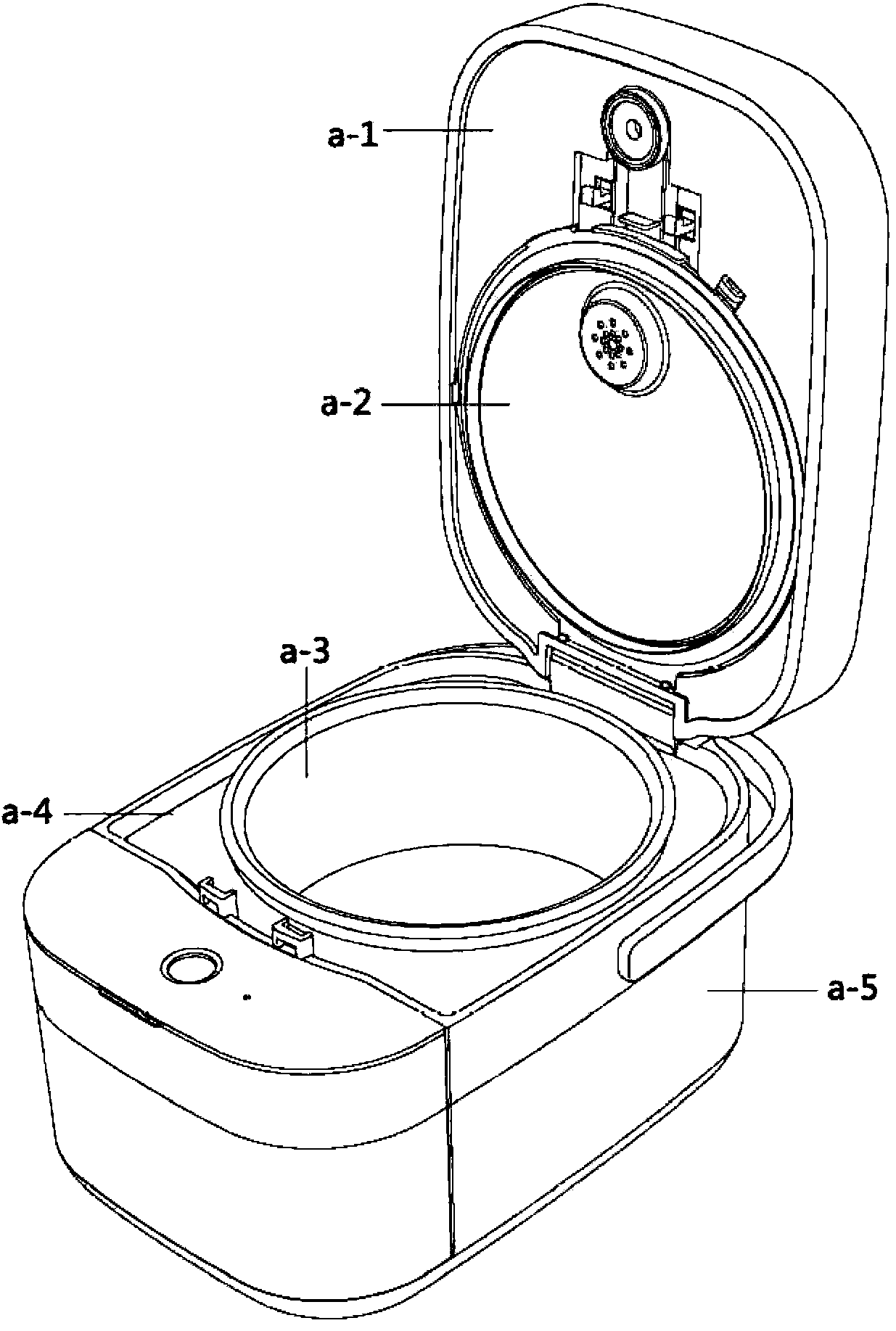
[0026] Such as figure 1 As shown, the cooking device provided by the preferred embodiment of the present invention takes an electric rice cooker as an example. The basic structure of the electric rice cooker includes an upper cover a-1, a detachable upper cover inner cover a-2, an inner pot a-3, an outer shell cover a-4 and Body base a-5. This is no different from an ordinary rice cooker. The special point described in this embodiment lies in the upper cover a-1, the upper cover detachable inner cover a-2 and the outer cover a-4 of the rice cooker.
[0027] The big difference from general rice cookers is that this embodiment has designed a set of steam collection unit, the specific structure is as follows figure 2 As shown, a steam duct b-2 is designed on the removable inner cover b-3 of the original rice cooker. When the rice cooker is working, the steam in the rice cooker will pass through the small hole b- on the inner cover b-3. 10 enters the steam duct b-2, and then flows to the cooling water storage box at the front end of the rice cooker shell.
[0028] The cooling water storage box is composed of a water storage box cover b-4 and a water storage box b-6. The cooling water storage box will be used to store a certain amount of cold water, and the steam will flow from the large round hole on the water storage box cover b-4 Flow into the cooling water storage box. Since the steam is not directly introduced into the water storage box b-6 containing cold water, it is necessary to further rush the steam to a sealed place for storage. Therefore, a set of steam collection box is designed under the cover b-4 of the water storage box.
[0029] The steam collection box includes two parts: the upper cover of the steam collection box b-5 and the steam collection box body b-8 (see Figure 4. These two parts are sealed and matched by the rubber ring on the upper steam collecting cover b-5. The steam collecting box d is tightly fitted with the large round hole on the water storage box cover b-4 at the protruding duct, so that the steam From the steam pipe b-2 to the steam collection box d, the steam will liquefy into small droplets when it is cold. When the water vapor enters the steam collection box, it will be affected by the temperature of the cold water in the water storage box b-6, and the steam will be collected The steam in the box will gradually liquefy into water, and the various odors generated during the cooking of the rice cooker will also be incorporated into the liquefied steam. In addition, since the heat in the pot will not be dissipated during the cooking process, water vapor above atmospheric pressure will enter a sealed steam collection box d, and the cooling water in the water storage box b-6 will not flow back into the pot through the steam pipe, thus heating At this time, the certain pressure generated in the pot will not drop sharply. When the pressure in the pot is greater than atmospheric pressure for a long time, and the food is cooked in this environment, the boiling point of the water will increase, and the cooking efficiency will be improved.
[0030] See figure 2 , Install the steam duct b-2 on the detachable inner cover b-3 of the rice cooker by snapping. The steam pipe is divided into two parts for easy cleaning (consisting of two pipes through a buckle buckle), which are also buckled in the form of a buckle. The buckle part is cushioned with a rubber ring to prevent steam leakage. The joint between the detachable inner cover b-3 and the steam duct b-2 is also provided with a rubber ring for sealing treatment to prevent air leakage. The other end of the steam pipe b-2 is wrapped with a sealing rubber ring b-1, and the sealing rubber ring b-1 is inserted into the large round hole of the water storage box cover b-4. Similarly, this can allow the steam to flow smoothly and prevent steam leakage.
[0031] Please see Image 6 , The connection between the water storage box cover b-4 and the steam collection box d also uses a plug-in method. A sealing rubber ring is designed under the large round hole of the pipe connecting the water storage box cover b-4 to the upper end of the steam collection box b-5. The steam enters the steam collection box d through the semicircular air holes of the steam collection box cover b-5. Please see Figure 4 versus Figure 5 ,When the steam enters the steam collection box d, in order to prevent excessive steam in the box from causing the steam to flow back during use, see Figure 5 , The middle position of the pipe at the upper end of the steam collection box cover b-5 is used as a separating surface. When a large amount of steam enters the right pipe e-1, a bend is formed in the pipe so that a large amount of steam can stay in the box. If the internal pressure increases, there will be too much steam that is too late to sink and liquefy, and it will be discharged out of the gas box through 3 small holes in the wall of the steam box cover b-5.
[0032] When in use, the water storage box needs to be filled with a certain amount of cold water. The amount of cold water must be at the position below the second row of small holes on the cover duct without the cover b-5 of the steam collection box. The specific operation process is to first align the steam collection box d with the round hole on the water storage box cover b-4 and screw it tightly, pour some water into the water storage box b-6, and close the water storage box cover b-4 , Please see Image 6. At this time, observe whether the amount of water in the water storage box b-4 is appropriate, and a simple water level detection switch is designed here. Please see image 3 , image 3 Shows the general structure of the water level display switch, see image 3 There is a positioning slot on the left side of the upper cover of the water storage box b-4. The slot is integrally formed with the cover of the water storage box, and there is a movable original piece with magnetic b-11 in the slot, which is called a float below. Put it into the positioning card slot, and block the card slot with a card slot cover c-1, so that the float has a certain amount of space for movement without falling out. When the water storage box b-6 is filled with water and the lid is closed, the float b-11 will float. The more water, the higher the float will float. The float b-11 is equipped with a magnetic sheet. According to the principle of magnetic field homogeneity attraction, the float can sense the magnetic switch in the cooker when it floats to a certain height. When the magnetic switch senses the magnetic force, it will start immediately, and the rice cooker completes the water storage box b-6. Confirmation can start the cooking program and start working.
[0033] See figure 2 In order to prevent the problem that the water storage box b-6 is not installed in place during use, especially the positioning groove b-9 is set under the water box, and the decorative surface cover b-7 of the water storage box is fixed on the bottom positioning groove b-9. Users cannot remove it. The water storage box b-6 is normally taken up and down. Only when a certain amount of water is put in the water storage box and the magnetic float b-11 rises to a specific position and touches the magnetic switch of the body, the rice cooker can start. In addition, the electric rice cooker of this embodiment can adopt the leak-proof assembly and detachable inner cover disclosed in Chinese patent CN201220620681.8. The steam collection assembly without the upper cover installed during use includes the detachable inner cover b-3 and the steam duct assembly ( b-1 and b-2), the rice cooker can’t be covered. This avoids misoperation caused by users forgetting to install accessories during operation, and eliminates potential unsafe factors in certain operations.
[0034] From the perspective of the external structural features of the product, the rice cooker of this embodiment is designed without a steam valve in a general sense. A set of steam collection unit is used internally, which collects gaseous water vapor and cools it into water using the principle that the steam is cooled and liquefied into water. The present invention uses this principle to eliminate steam and odor.

PUM

no PUM

Description & Claims & Application Information

We can also present the details of the Description, Claims and Application information to help users get a comprehensive understanding of the technical details of the patent, such as background art, summary of invention, brief description of drawings, description of embodiments, and other original content. On the other hand, users can also determine the specific scope of protection of the technology through the list of claims; as well as understand the changes in the life cycle of the technology with the presentation of the patent timeline. Login to view more.

Similar technology patents

Cooking equipment, cooking method, cooking device and storage medium

Owner:FOSHAN SHUNDE MIDEA ELECTRICAL HEATING APPLIANCES MFG CO LTD

Electric smoking oven

InactiveCN102365991AImprove cooking efficiencyGuaranteed Cooking ConsistencyMeat/fish preservationElectricityEngineering
Owner:TIANJIN HEIZI FOOD

Classification and recommendation of technical efficacy words

  • Improve cooking efficiency
  • Not easy to lose

All-intelligent chef robot

Owner:BEIJING ROC THEURGY TECH

Sprinkling deep frying pan

InactiveCN101991366AFast warm-up and low energy consumptionImprove cooking efficiencyDeep fat fryersImpellerFrying-pans
Owner:周林斌
Why Eureka
Try Eureka