
Single drive linkage type lower limb power assisting exoskeleton

A linkage and single-drive technology, applied in passive exercise equipment, artificial legs, physical therapy, etc., can solve the problems of waste of functions and high cost, and achieve the effect of reducing design, reducing difficulty, and increasing the scope of application

Active Publication Date: 2014-10-01
HARBIN INST OF TECH
View PDF11 Cites 29 Cited by
  • Summary
  • Abstract
  • Description
  • Claims
  • Application Information

AI Technical Summary

Problems solved by technology

[0008] In order to solve the existing exoskeleton design, the present invention basically adopts motor or hydraulic pressure to independently control the hip joint and knee joint, so as to realize the high degree of freedom and high adaptability of the exoskeleton mechanism, but different groups of people have different requirements for the exoskeleton. Different, so high adaptability will bring the problem of functional waste and high cost, and provide a single-drive linkage lower limb power-assisted exoskeleton

Method used


Image

  • Single drive linkage type lower limb power assisting exoskeleton
  • Single drive linkage type lower limb power assisting exoskeleton
  • Single drive linkage type lower limb power assisting exoskeleton

Examples


specific Embodiment approach 1

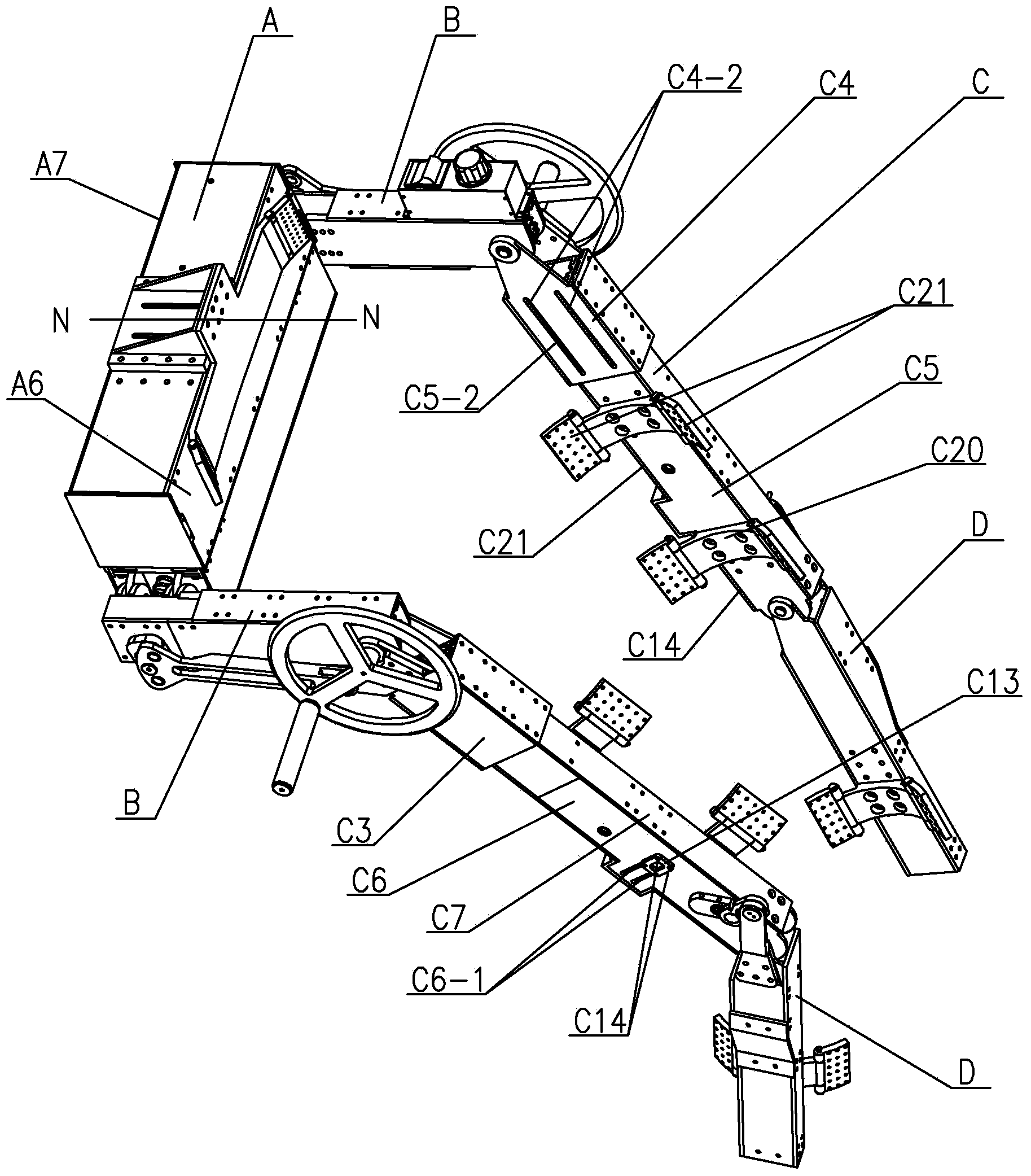
[0045] Specific implementation mode one: combine Figure 1 to Figure 15 Describe this embodiment, this embodiment includes back module A, two waist modules B, two thighs C and two calves D,

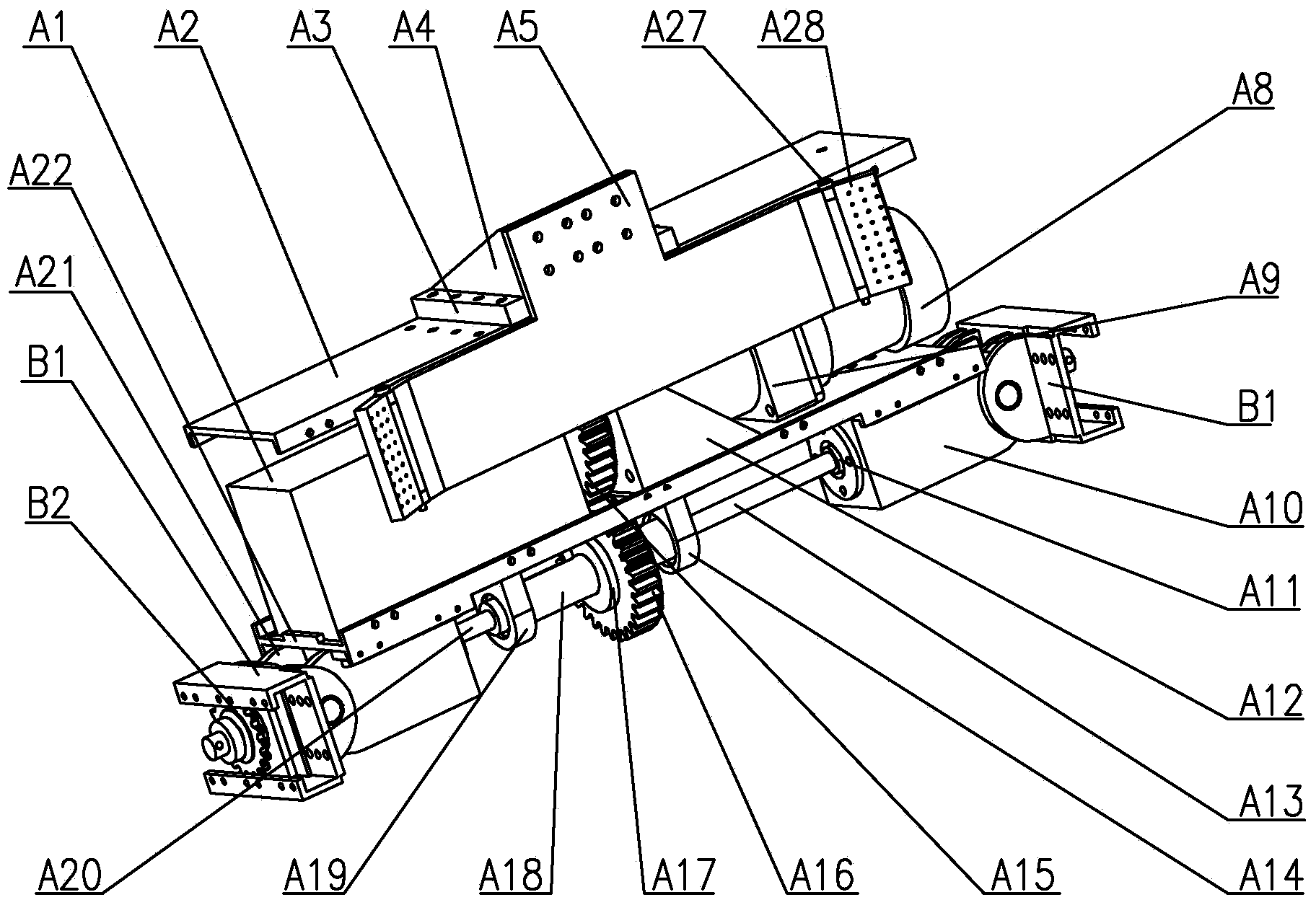
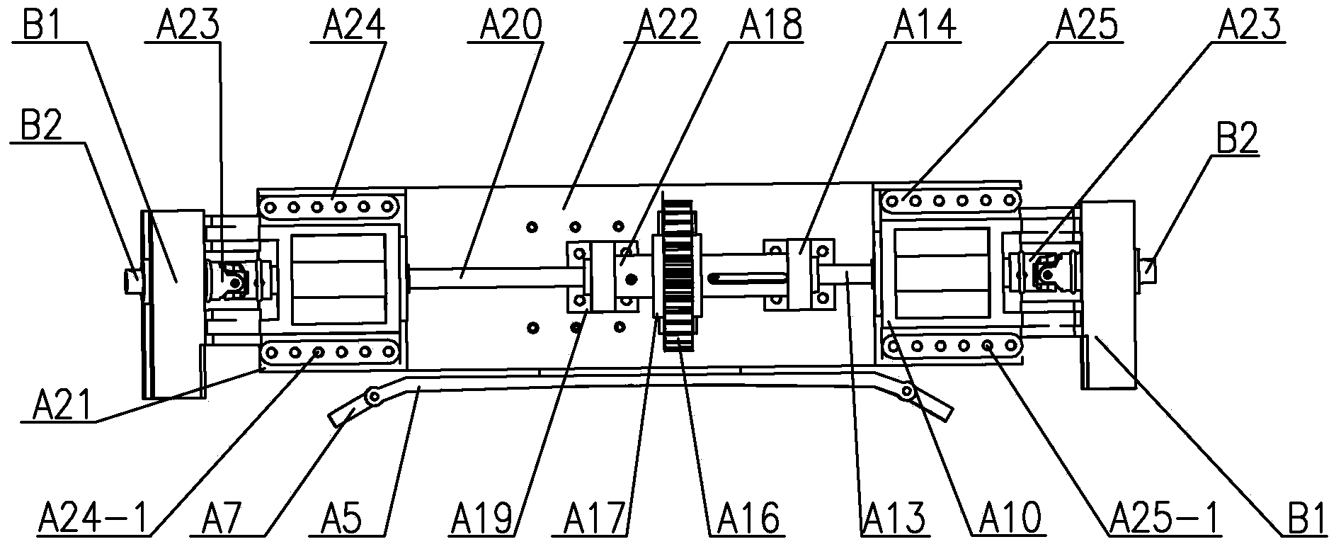
[0046] Back module A includes lithium battery A1, slot plate A2, slider A4, backboard A5, front baffle A6, rear baffle A7, motor A8, reducer A9, right back connector A10, motor seat A12, right shaft A13, right base A14, driving gear A15, driven gear A16, left base A19, expansion sleeve A17, coupling sleeve A18, left shaft A20, left back connector A21, main board A22, left connecting plate A24, right The connecting plate A25, two stoppers A3, two bearings A11 and two universal couplings A23, the lithium battery A1 and the motor base A12 are fixed on the upper end surface of the main board A22, and the lithium battery A1 and the motor base A12 are connected through wires connection, the reducer A9 is fixed on the motor seat A12, the input end of the reducer A9 is connected to the motor A8,...

specific Embodiment approach 2

[0059] Specific implementation mode two: combination figure 2 This embodiment will be described. The motor A8 of this embodiment is a DC brushless motor. Other components and connections are the same as those in the first embodiment.

specific Embodiment approach 3

[0060] Specific implementation mode three: combination figure 2 Describe this embodiment, the back module A of this embodiment also includes two backrest pins A27 and two rotating blocks A28, and the two ends of backboard A5 are respectively provided with a rotating block A28, and this rotating block A28 connects with the backrest through a backrest pin A27 Plate A5 is hinged. Other compositions and connections are the same as those in Embodiment 1 or 2.


PUM


Abstract

The invention discloses a single drive linkage type lower limb power assisting exoskeleton, relates to a lower limb exoskeleton used for power assisting and walking, and aims to solve the problem that conventional exoskeleton design basically adopts a motor or hydraulic pressure to conduct independent control on a hip-joint and knee joints. The lower limb power assisting exoskeleton comprises a back module, two waist modules, two thighs and two cruses; the two waist modules are arranged at the two ends of the back module; thigh drive sprockets and a third crank shaft on the waist module are mounted on the output shaft of a universal coupling on the back module sequentially from inside to outside; each waist module corresponds to a thigh and a crus; front ends of adjusting outer side plates and adjusting inner side plates on the thighs are hinged to the central shafts of double-row chain wheels on the waist module; two lifting lugs on the cruses are hinged to the connecting shafts on the thighs. The lower limb power assisting exoskeleton is used for assisting the old and disabled, medical rehabilitation, and the like.

Description

technical field [0001] The invention relates to a lower limb exoskeleton for assisting walking, in particular to a single-drive linkage lower limb assisting exoskeleton. Background technique [0002] At present, the research on exoskeleton power-assisted devices is gradually emerging, and has a wide range of application prospects, such as helping the elderly and the disabled, medical rehabilitation, industrial production, earthquake rescue, individual combat and other fields. The general power-assisted exoskeleton has the following characteristics: it can detect the movement intention of the human body; the joint degrees of freedom and joint rotation space are similar to the human body; it has the necessary active drive of the joints to assist the output; it has its own control system and energy system; it has certain safety defense mechanism. [0003] According to the purpose of power transmission, power-assisted exoskeleton can be divided into two situations: exoskeleton ...

Claims


Application Information

Patent Timeline
Patent Type & Authority Applications(China)
IPC IPC(8): A61F2/60A61H1/00
Inventor 朱延河赵杰蔡雪风
Owner HARBIN INST OF TECH
Learn More