
A real-time compensation device and method for comprehensive error of spindle

A comprehensive error, real-time compensation technology, applied in other manufacturing equipment/tools, metal processing mechanical parts, maintenance and safety accessories, etc., can solve the problems of precision machining errors, slow response speed, complex methods, etc., to achieve rapid measurement and compensation , Improve the effect of error compensation accuracy

Inactive Publication Date: 2016-08-24
GUANGDONG UNIV OF TECH
View PDF6 Cites 1 Cited by
  • Summary
  • Abstract
  • Description
  • Claims
  • Application Information

AI Technical Summary

Problems solved by technology

In the current technology, basically only the synchronous error of the spindle is detected or compensated, or only the non-synchronized error is detected or corrected, and the method adopted is relatively complicated, requiring various cumbersome calculations, the response speed is slow, and it cannot be comprehensively analyzed. Respond to the error of the spindle, resulting in a large error in precision machining

Method used

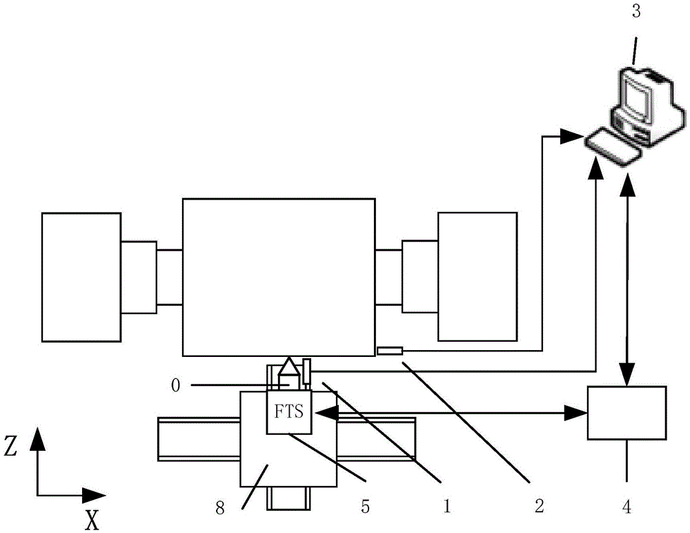
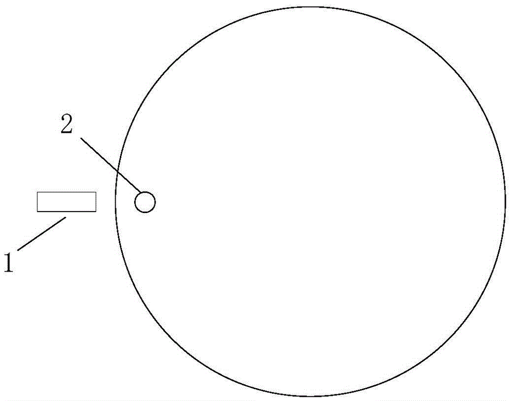
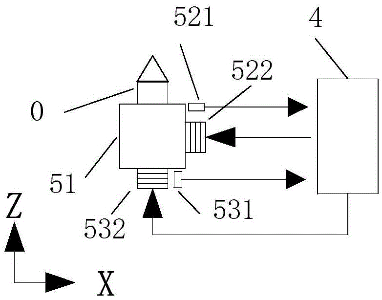

Image

  • A real-time compensation device and method for comprehensive error of spindle
  • A real-time compensation device and method for comprehensive error of spindle
  • A real-time compensation device and method for comprehensive error of spindle

Examples


Embodiment 1

[0050] refer to Figure 1~Figure 3 , a spindle comprehensive error real-time compensation device, comprising a radial capacitive displacement sensor 1, an axial capacitive displacement sensor 2, a control computer 3, a two-degree-of-freedom fast-tool servo controller 4 and a two-degree-of-freedom fast-tool servo unit 5, the radial capacitive displacement The output end of the sensor 1 is connected with the first input end of the control computer 3, the output end of the axial capacitive displacement sensor 2 is connected with the second input end of the control computer 3, and the two-degree-of-freedom fast knife servo controller 4 is respectively connected with the control computer 3 and the control computer 3. Two-degree-of-freedom fast-knife servo unit 5 connections;

[0051] The two-degree-of-freedom fast tool servo unit 5 is connected to the processing tool 0, the radial capacitive displacement sensor 1 is installed on one side of the processing tool 0 and its axis is per...

Embodiment 2

[0060] A real-time compensation method for a comprehensive error of a spindle, comprising:

[0061] S1. Use the radial capacitive displacement sensor to collect the real-time radial displacement of the workpiece and send it to the control computer, and at the same time use the axial capacitive displacement sensor to collect the real-time axial displacement of the workpiece and send it to the control computer;

[0062] S2. The control computer receives the real-time radial displacement and axial displacement of the workpiece and compares them with the preset radial displacement and preset axial displacement respectively, and then calculates the radial error and axial error of the workpiece and sends them to Two-degree-of-freedom fast-tool servo controller; the preset radial displacement and preset axial displacement are set processing parameters for the workpiece. For example, if there is a difference between the real-time radial displacement and the preset radial displacement, ...


PUM


Abstract

The invention discloses a device and a method for compensating a composition error of a main shaft in real time. The device comprises a radial capacitance displacement sensor, an axial capacitance displacement sensor, a control computer, a two-degree of freedom sharp knife servo controller and a two-degree of freedom sharp knife servo unit, wherein the output end of the radial capacitance displacement sensor is connected with the first input end of the control computer; the output end of the axial capacitance displacement sensor is connected with the second input end of the control computer; the two-degree of freedom sharp knife servo controller is respectively connected with the control computer and the two-degree of freedom sharp knife servo unit; the two-degree of freedom sharp knife servo unit is connected with a processing cuter; the radial capacitance displacement sensor is arranged at one side of the processing cutter, and the axial line thereof is vertically intersected with the axial line of a work-piece; the axial capacitance displacement sensor is arranged on one end face of the work-piece, and the axial line thereof is vertical to the end face of the work-piece. The device and the method for compensating the composition error of the main shaft in real time can perform on-line and real-time measurement and compensation on the composition error simply, rapidly and comprehensively, and can be widely applied to the field of precision machine tool machining.

Description

technical field [0001] The invention relates to the field of precision machine tool processing, in particular to a real-time compensation device and method for comprehensive error of a spindle used for processing the microstructure of a roller on an ultra-precision machine tool. Background technique [0002] The microstructures on many optical devices are processed by roll forming, and the rollers used in roll forming are mostly processed by single-point diamond ultra-precision machine tools. Due to the very small size of the microstructure, the requirements for the shape accuracy and surface roughness of the structure are very high, which also puts forward very high requirements for the machining accuracy of the machine tool. [0003] Spindle is an important component widely used in ultra-precision machine tools, and its motion accuracy has decisive significance for processing quality. With the development of the air bearing spindle, the precision of the spindle has been g...

Claims


Application Information

Patent Timeline
Patent Type & Authority Patents(China)
IPC IPC(8): B23Q11/00B23B19/02
CPCB23Q17/007B23Q23/00
Inventor 刘明宇张志辉孔令豹李荣彬杜雪陈新
Owner GUANGDONG UNIV OF TECH
Learn More