
Gear Drilling Tooling

A drilling tool and gear technology, applied in positioning devices, clamping devices, manufacturing tools, etc., can solve the problems of scrapped gears, low drilling efficiency, wrong number of teeth, etc., to improve concentricity, improve drilling efficiency, The effect of improving efficiency

Active Publication Date: 2016-09-07
双环传动(重庆)精密科技有限责任公司
View PDF5 Cites 4 Cited by
  • Summary
  • Abstract
  • Description
  • Claims
  • Application Information

AI Technical Summary

Problems solved by technology

Drilling in this way is not only inefficient, but also easy to count the wrong number of teeth and cause the gear to be scrapped

Method used


Image

  • Gear Drilling Tooling
  • Gear Drilling Tooling
  • Gear Drilling Tooling

Examples


Embodiment Construction

[0021] The present invention will be described in detail below in conjunction with accompanying drawing, as Figures 1 to 4 Shown:

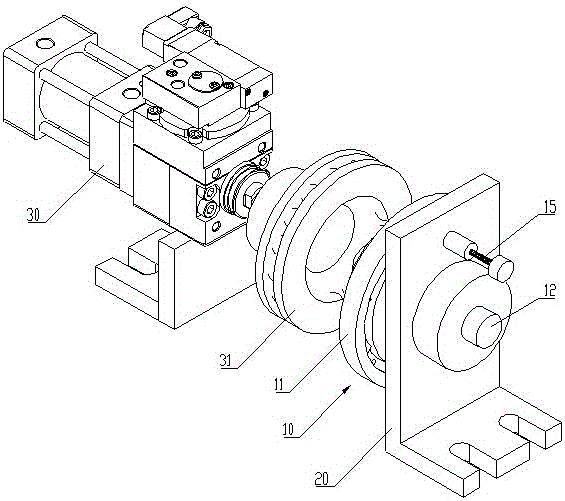
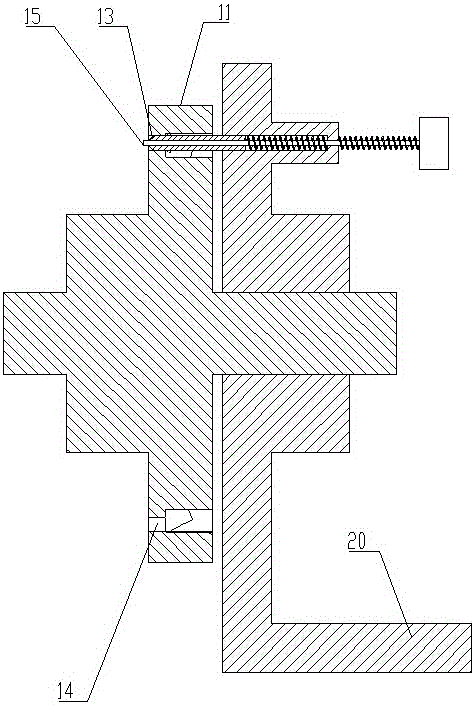
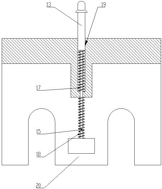
[0022] The gear drilling tool of this embodiment includes an angle positioning mechanism 10 capable of automatically adjusting the gear angle so that the oil holes in the gear circumference are evenly distributed and a base 20 for installing the angle positioning mechanism. The angle positioning mechanism 10 includes an angle positioning mechanism that can simultaneously The positioning turntable 11 of the shaft fixed gear, the positioning shaft 12 coaxially arranged on the positioning turntable and the positioning thimble 13 arranged on the base for fixing the position of the positioning turntable, one end of the positioning shaft 12 is inserted into the base 20 , and rotate with the base 20, the circumferential direction of the positioning turntable 11 is evenly provided with a plurality of through holes 14 arranged axially along the positionin...


PUM


Abstract

The invention discloses a gear drilling tool which comprises an angle location mechanism and a base. The angle location mechanism comprises a locating turnplate capable of coaxially fixing a gear, a locating shaft coaxially arranged on the locating turnplate and locating ejector pins arranged on the base and used for fixing the position of the locating turnplate. One end of the locating shaft is inserted in the base and is in running fit with the base, a plurality of through holes formed in the axial direction of the locating turnplate are evenly formed in the circumferential direction of the locating turnplate, and the locating ejector pins are in sliding fit with the base in the axial direction of the locating turnplate to be used for being inserted in the through holes to fix the circumferential position of the locating turnplate. The gear drilling tool achieves rapid location through the matching of the through holes in the locating turnplate and the locating ejector pins, improves drilling efficiency and guarantees drilling precision.

Description

technical field [0001] The invention relates to a gear processing device, in particular to a gear drilling tool which can improve the efficiency of gear drilling. Background technique [0002] In the prior art, when the transmission gear is drilled between the teeth, after each drilling, manual visual inspection is required to rotate the gear for positioning, and then perform the next drilling. Drilling with this method not only has low drilling efficiency, but also easily counts the wrong number of teeth and causes the gear to be scrapped. [0003] In view of the above-mentioned deficiencies, the inventor has designed a gear drilling tool to solve the above-mentioned problems. Contents of the invention [0004] In view of this, the object of the present invention is to provide a gear drilling tool, which has the advantages of high drilling efficiency and precise gear positioning when drilling gears. [0005] The present invention solves the above problems by the followi...

Claims


Application Information

Patent Timeline
Patent Type & Authority Patents(China)
IPC IPC(8): B23Q16/02
CPCB23Q3/08B23Q16/065B23Q2703/04
Inventor 王久强马孝银
Owner 双环传动(重庆)精密科技有限责任公司
Learn More