
Protective film cutting device

A protective film and cutting technology, which is applied in metal processing and other directions, can solve the problems of increasing the burden on enterprises, low cutting precision, and increasing costs, and achieve the effects of reducing uneven cutting, improving the effect of film sticking, and saving use costs

Inactive Publication Date: 2014-10-01
XINGWEI COMP KUNSHAN
View PDF7 Cites 2 Cited by
  • Summary
  • Abstract
  • Description
  • Claims
  • Application Information

AI Technical Summary

Problems solved by technology

A protective film must be pasted on some chassis to prevent the chassis from being damaged during handling and use. When pasting the protective film, the used protective film needs to be cut off from the rolled protective film. When cutting, scissors are often used for manual cutting. The manual cutting method has the following disadvantages: 1. The manual cutting speed is slow, the efficiency is low, and it cannot be processed quickly
2. It is impossible to position the roll-shaped protective film, and the cutting accuracy is low. It often requires two people to cooperate to complete the work, which wastes a lot of human resources and increases the cost.
3. Manually cut directly with scissors, the cutting is easy to be skewed and uneven, resulting in waste of protective film and increasing the burden on the enterprise

Method used


Image

  • Protective film cutting device

Examples


Embodiment Construction

[0013] The present invention will be further described below in conjunction with the accompanying drawings.

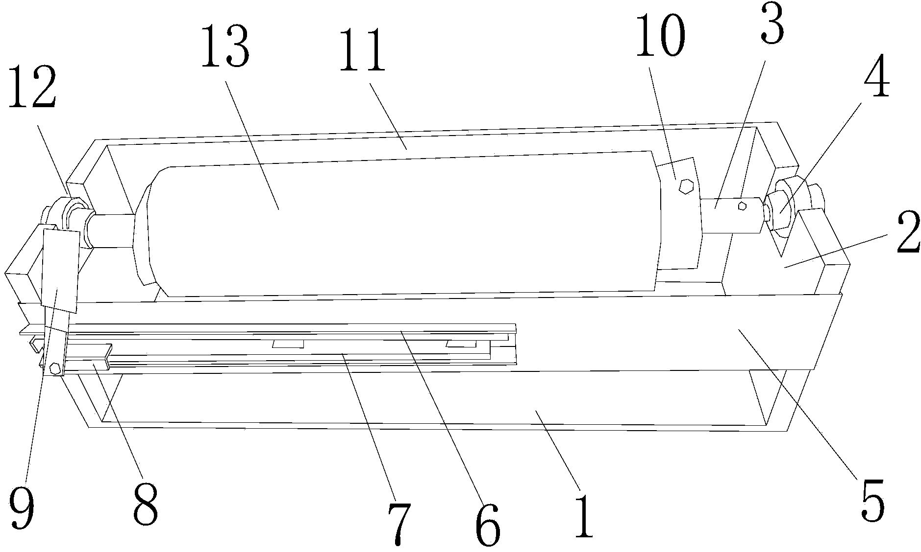
[0014] Such as figure 1 As shown, a protective film cutting device includes a bottom plate 1, side plates 2 located on both sides of the bottom plate 1, a rotating shaft 3, a bearing 4, a front panel 5, a slide rail frame 6, a slide rail 7, a slider 8 and a cutting The knife 9 has a notch 12 on the two side plates 2 respectively, and a slot is provided on the inner wall of the notch 12, the bearing 4 is installed in the notch 12 through the slot, and the rotating shaft 3 is detachably mounted on the Between the two bearings 4, a front panel 5 is arranged at the front of the two side plates 2, and a slide rail frame 6 is arranged on the front surface of the front panel 5, and a slide rail 7 is arranged on the slide rail frame 6, and a slide rail 7 is arranged on the slide rail 7. A slide block 8 capable of sliding along the slide rail 7 is arranged on the top, and the ...


PUM


Abstract

The invention discloses a protective film cutting device. The protective film cutting device comprises a base plate and two side plates which are located on the bilateral sides of the base plate respectively. The protective film cutting device is characterized by also comprising a rotating shaft, bearings, a front panel, a sliding rail frame, a sliding rail, a sliding block and a cutter; each side plate is provided with a gap; the inner wall of each gap is provided with a clamping groove; each bearing is arranged in each gap through the corresponding clamping groove; the rotating shaft is detachably arranged between the two bearings; the front portions of the two side plates are provided with the front panel; the front surface of the front panel is provided with the sliding rail frame which is provided with the sliding rail; the sliding rail is provided with the sliding block which can slide along the sliding rail; the cutter is hinged to the front surface of the sliding block. According to the protective film cutting device, the structure is simple, the use is convenient, the rapid positioning can be achieved, the machining frequency can be improved, the non-uniform cutting of protective films can be reduced, the lamination yield can be improved, and the use cost can be reduced.

Description

technical field [0001] The invention relates to a cutting device, in particular to a protective film cutting device. Background technique [0002] In terms of function, the protective film is to put a film on the physical object we want to protect, so that it will not be damaged or the like. A protective film must be pasted on some chassis to prevent the chassis from being damaged during handling and use. When pasting the protective film, the used protective film needs to be cut off from the rolled protective film. When cutting, scissors are often used for manual cutting, and the manual cutting method has the following disadvantages: 1. The manual cutting speed is slow, the efficiency is low, and fast processing cannot be performed. 2. The roll-shaped protective film cannot be positioned, and the cutting accuracy is low. It often requires the cooperation of two people to complete the work, which wastes a lot of human resources and increases the cost. 3. Manually use scisso...

Claims


Application Information

Patent Timeline
Patent Type & Authority Applications(China)
IPC IPC(8): B26D1/04B26D7/01
Inventor 陆新庆
Owner XINGWEI COMP KUNSHAN
Learn More