Liquid pump with outside mounted spring

A liquid pump, external technology, applied in dispensing device, closing, packaging, etc., can solve the problems of blocked rotation of the pressure head, limited stroke range, large size, etc., to avoid exposure, increase the pressing stroke, and increase the range Effect

Active Publication Date: 2014-10-01
丁要武
View PDF3 Cites 5 Cited by
  • Summary
  • Abstract
  • Description
  • Claims
  • Application Information

AI Technical Summary

Problems solved by technology

The increased frictional force will hinder the normal sliding of the surfaces at both ends of the spring on the supporting surfaces of the upper spring seat 152 and the lower spring seat 121, causing the rotation of the pressure head 110 relative to the mouthpiece 120 to be hindered, thus affecting the position of the pressure head in the lock position and Smooth transition between release positions
In some more unfavorable cases, the end face of the spring wire can squeeze into the bearing surface of the spring seat made of relatively soft material (usually plastic), so that the indenter cannot rotate relative to the brace at all and cannot complete the process. Transition between lock position and release position
[0006] Secondly, since the spring 130 is arranged outside the liquid storage tank and located in the neck area of ​​the liquid pump, this type of spring-mounted liquid pump inherently has the problem of large size.
Moreover, since the indenter sleeve 111 and the mouthpiece sleeve 122 must at least partially overlap to cover the spring 130 and prevent it from being exposed, this limits the travel range of the indenter 110 moving up and down relative to the mouthpiece 120
For liquid pumps requiring a larger stroke range, the length of the neck area has to be increased, resulting in an unacceptable overall height of the product container

Method used


Image

  • Liquid pump with outside mounted spring
  • Liquid pump with outside mounted spring
  • Liquid pump with outside mounted spring

Examples


Embodiment Construction

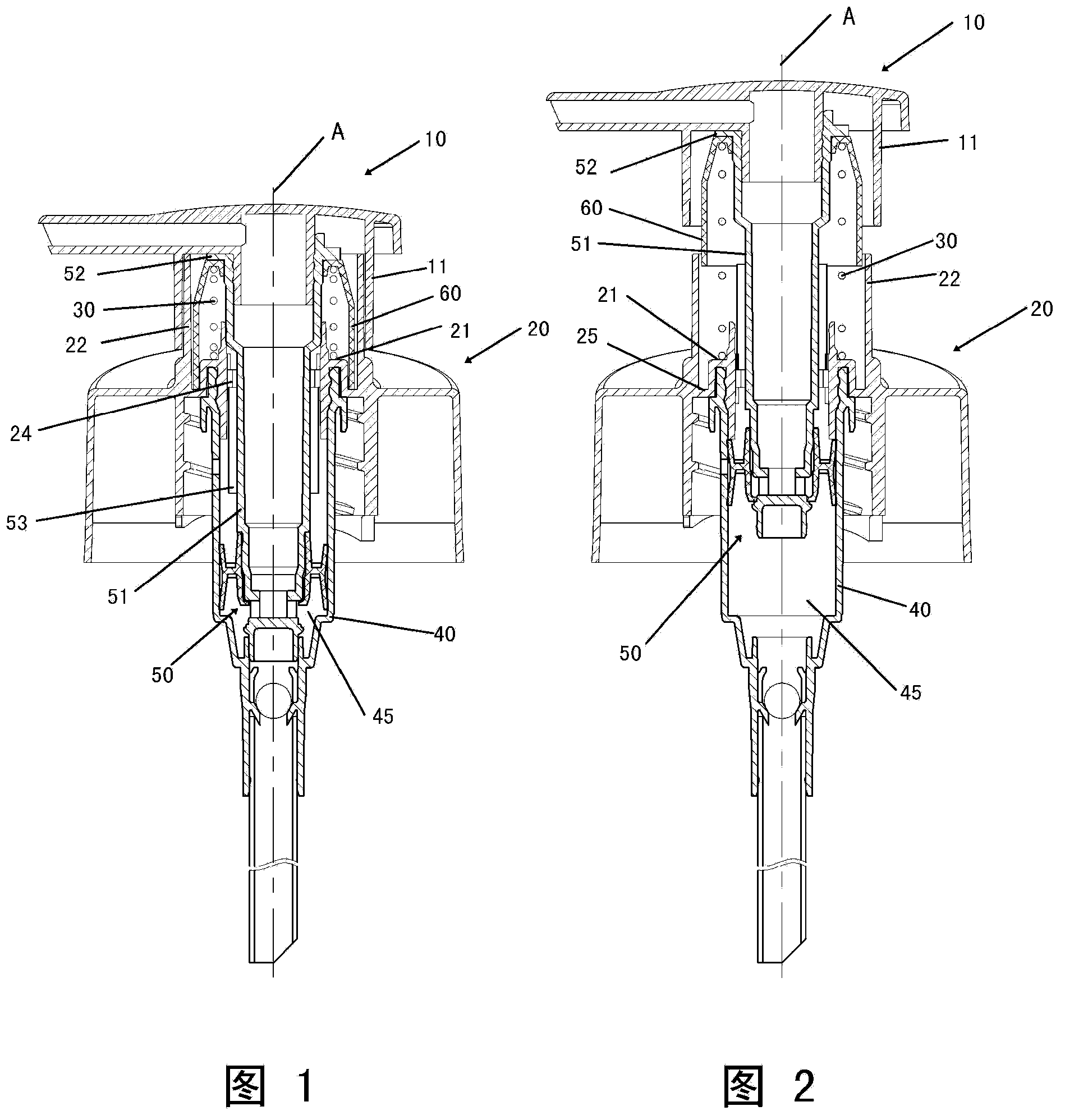
[0025] First of all, by the way, the "up" and "down" mentioned in this article are determined relative to the liquid pump being placed in a vertical orientation (that is, the liquid pump is set so that its axis direction is consistent with the vertical direction) .

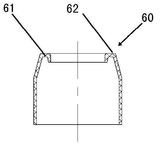
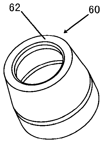
[0026] see figure 1 -7, which shows an exemplary embodiment of the present invention. The spring external liquid pump mainly includes a pressure head 10 with an outlet, a mouthpiece 20 for connecting with a container (not shown) to fix the liquid pump at the opening of the container, a liquid storage tank 45 formed by a cylinder 40, The piston assembly 50 is slidably arranged in the liquid storage tank 45 in the axial direction and is connected with the pressure head 10 so as to reciprocate up and down in the liquid storage tank 45 in the axial direction, and the piston assembly 50 surrounds the piston between the pressure head 10 and the mouthpiece 20 The piston rod 51 of the assembly 50 is provided with a res...


PUM


Abstract

The invention provides a liquid pump with an outside mounted spring. The liquid pump comprises a pressure head, a tooth sleeve, a liquid storage tank formed by a cylinder, a piston assembly, and a reset compression spring arranged between the pressure head and the tooth sleeve and used for enabling the pressure head to upwards move in the axial direction corresponding to the tooth sleeve. The pressure head is provided with an upper spring base; and the tooth sleeve is provided with a lower spring base. The pressure head has a bushing extending downwards; the tooth sleeve has a bushing extending upwards; and the two bushings can be telescopically nested with each other. According to the liquid pump, the upper end of the spring is pressed against the upper spring base through being sleeved in a sleeve piece; and in an upper dead center position of pressing travel, the lower end of the bushing of the pressure head is separated from the upper end of the bushing of the tooth sleeve in the axial direction, and the lower end of the sleeve piece extends to a position lower than the upper end of the bushing of the tooth sleeve. The liquid pump can effectively solve the problem of unsmooth rotation of the pressure head or even getting stuck corresponding to the tooth sleeve, and can realize the needed pressing travel with relatively smaller size.

Description

technical field [0001] The invention relates to the field of push-type liquid pumps, and more specifically relates to a spring-mounted liquid pump in which a spring is arranged outside a liquid storage tank. Background technique [0002] The push-type liquid pump is generally installed at the opening of the container, and is used for pumping and distributing the liquid product in the container out of the container through a manual pressing operation by a user for use. This type of liquid pump has a return compression spring for returning the pump head to its original position after the user removes the downward pressure on the pump head, and at the same time pumps the liquid product in the container to the In the storage tank of the liquid pump for the next pump pressure distribution. At present, there is a push-type liquid pump on the market, such as Figure 8 and 9 As shown, it generally includes a pressure head 110 with an outlet, a mouthpiece 120 for connecting with a ...

Claims


Application Information

Patent Timeline
Patent Type & Authority Applications(China)
IPC IPC(8): B65D47/34B65D83/00
CPCB05B11/1023B05B11/1074B05B11/1067
Inventor 丁要武
Owner 丁要武
Why Eureka
Try Eureka